Full-duplex signal transmission device based on optical communication

A signal transmission, full-duplex technology, applied in the field of optical communication, can solve the problems of complicated communication structure design and increased cost.

Pending Publication Date: 2019-06-25
保定市天河电子技术有限公司
View PDF0 Cites 6 Cited by
  • Summary
  • Abstract
  • Description
  • Claims
  • Application Information

AI Technical Summary

Problems solved by technology

However, more optical transmitters and optical receivers need to be configured, which not only

Method used


Image

  • Full-duplex signal transmission device based on optical communication
  • Full-duplex signal transmission device based on optical communication
  • Full-duplex signal transmission device based on optical communication

Examples


Embodiment Construction

[0042] In order to make the purpose, technical solution and advantages of the present application clearer, the technical solution of the present application will be clearly and completely described below in conjunction with specific embodiments of the present application and corresponding drawings. Apparently, the described embodiments are only some of the embodiments of the present application, rather than all the embodiments. Based on the embodiments in this application, all other embodiments obtained by persons of ordinary skill in the art without making creative efforts belong to the scope of protection of this application.

[0043] The technical solutions provided by various embodiments of the present application will be described in detail below in conjunction with the accompanying drawings.

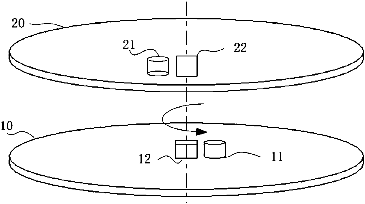
[0044] image 3 A full-duplex signal transmission device based on optical communication is provided for a specific embodiment of the present application. Such as image 3 As sho...


PUM


Abstract

The specific embodiment of the invention provides a full-duplex signal transmission device based on optical communication. The device comprises a component 10 and a component 20, wherein components rotate relative to each other about the same rotation axis. The component 10 is provided with a light emitter 11 and a light receiver 12. The component 20 is provided with a light emitter 21 and a lightreceiver 22. The light emitter 11 and the light receiver 22 use spectral communication of a first wavelength. The light emitter 21 and the light receiver 12 use spectral communication of a second wavelength. The photosensitive surface of the light receiver 12 of the component 10 and the photosensitive surface of the light receiver 22 of the component 20 are arranged at the relative rotation centers of the components 10 and 20. According to the invention, the photosensitive surfaces of two light receivers are arranged at the relative rotation centers of two components respectively, which keepsthe intensity of the signals received by the light receivers unchanged; the bit error rate is reduced; and the transmission quality and efficiency are improved.

Description

technical field [0001] The present application relates to the technical field of optical communication, in particular to a full-duplex signal transmission device based on optical communication. Background technique [0002] In order to solve the problem of two-way data communication between relatively rotating parts, slip ring technology was adopted in the early stage. However, due to the inherent wear and tear of slip rings, the average life span is generally around hundreds of millions of revolutions. For example, for LiDAR, a device that needs to work continuously and rotate at high speed, the slip ring can only last for 1 to 2 years. Therefore, slip rings cannot meet the design requirements of most products; moreover, due to the influence of contact wear, there will be great hidden dangers in the quality of signal communication. [0003] With the development of optical communication technology, the use of optical communication for data transmission between two relative...

Claims


Application Information

Patent Timeline
IPC IPC(8): G01S7/481
Inventor 武旭辉张健王勇尹金茹
Owner 保定市天河电子技术有限公司
Why Eureka
Try Eureka