Camera calibration and flat field correction device, camera calibration method and flat field correction method

A camera calibration and correction device technology, which is applied in image data processing, instruments, calculations, etc., can solve the problems of high price, large volume, and large radiation energy of the integrating sphere, and achieve the effect of fast and accurate camera calibration and flat field correction

Inactive Publication Date: 2019-06-25
GEOPTICS SEQUENCING EQUIP CO LTD
View PDF7 Cites 9 Cited by
  • Summary
  • Abstract
  • Description
  • Claims
  • Application Information

AI Technical Summary

Problems solved by technology

However, the integrating sphere is expensive, bulky, and the radiant energy is...

Method used


Image

  • Camera calibration and flat field correction device, camera calibration method and flat field correction method
  • Camera calibration and flat field correction device, camera calibration method and flat field correction method
  • Camera calibration and flat field correction device, camera calibration method and flat field correction method

Examples


Embodiment 1

[0037] This embodiment provides a camera calibration and flat field correction device. This device is mainly used for camera calibration and flat field correction to correct the imaging gray value of each pixel of the camera to be equal or nearly equal to meet the needs of use, such as calibration and flat field correction. Calibrate the fluorescence imaging camera on the gene sequencer.

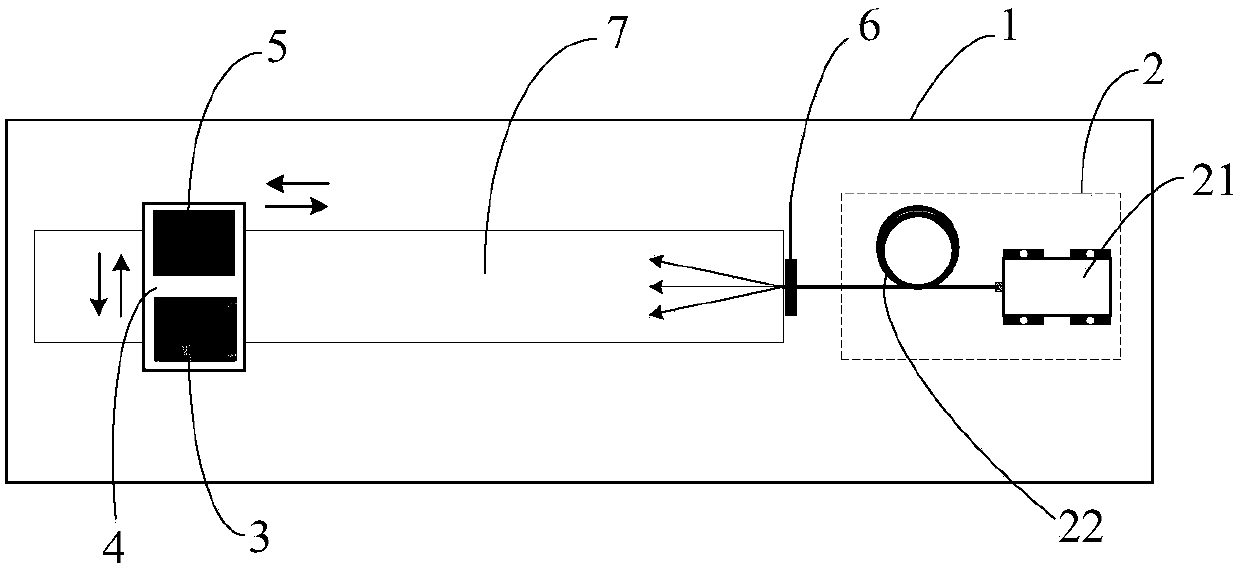
[0038] Such as figure 1 As shown, the camera calibration and flat field correction device of this embodiment mainly includes a camera obscura 1 , a light source generator 2 , a reference camera 3 and a mobile platform 4 .

[0039] The dark box 1 is a light-tight sealed box. The dark box 1 is rectangular and placed horizontally. All other components of the device are installed in the dark box 1 to avoid interference from external light to the detection.

[0040] The light source generator 2 is installed at one end in the dark box 1. The light source generator 2 includes an LED light source 2...

Embodiment 2

[0054] This embodiment provides a camera calibration method, which is implemented based on the camera calibration and flat field correction device in the first embodiment above.

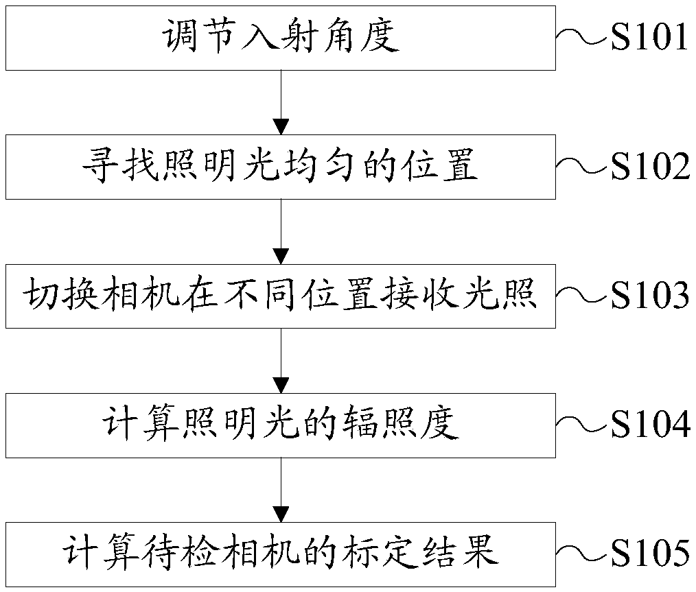
[0055] Such as figure 2 As shown, the camera calibration method in this embodiment includes the following steps:

[0056] S101: adjusting the incident angle;

[0057] Adjust the optical axis of the illumination light through the installation end on the upper end of the optical fiber mounting bracket 6 to keep it horizontal, and adjust the reference camera 3 to align with the emission end of the optical fiber 22 through the vertical movement of the mobile platform 4, so that the illumination light emitted by the LED light source 21 is vertically incident on the Base camera 3;

[0058] S102: Find a position where the illumination light is uniform;

[0059] Turn on the LED light source, observe the uniformity of the image in real time from the image of the reference camera 3, and adjust the distance...


PUM

PropertyMeasurementUnit
Lengthaaaaaaaaaa

Abstract

The invention discloses a camera calibration and flat field correction device, a camera calibration method and a flat field correction method. The camera calibration and flat field correction device comprises a camera obscura; a light source generator which comprises an LED light source and an optical fiber connected with the LED light source; A reference camera; and a Mobile station. The camera calibration and flat field correction device adopts an LED light source with adjustable brightness as an emission light source; the reference camera is used as a detector of illumination light irradiance; the camera to be detected and the reference camera are mounted on a movable moving table; The device can adjust the irradiance of illumination light by adjusting the brightness of the LED light source or adjusting the distance between the camera to be detected and the reference camera and the LED light source. wherein the reference camera is an area array detector and can also be used for detecting the irradiation uniformity of illumination light, so that the device is composed of cheap components and can carry out rapid and accurate camera calibration and flat field correction.

Description

technical field [0001] The invention relates to the technical field of camera imaging correction, in particular to a camera calibration and flat field correction device, a camera calibration method and a flat field correction method. Background technique [0002] Ideally, when the irradiance received by each pixel of the camera is equal, that is, the entire target surface of the detector is irradiated uniformly, the gray value of all pixels in the image should be equal. In fact, for any CCD and CMOS camera, each pixel produces different gray values ​​for the same irradiance, which is called the non-uniformity of the detector's response. The causes of response non-uniformity include: the structural material and manufacturing process of the camera's CCD or CMOS chip itself have local differences; the spectral response function of each pixel is different; the difference in readout noise and dark current noise, etc. The purpose of the flat field correction is to correct the abo...

Claims


Application Information

Patent Timeline
IPC IPC(8): G06T7/80
Inventor 常松涛段锁城杨旺
Owner GEOPTICS SEQUENCING EQUIP CO LTD
Why Eureka
Try Eureka