
Auxiliary equipment for installation of power distribution cabinet

An auxiliary equipment and installation technology, which is applied in the field of auxiliary equipment for installation of power distribution cabinets, can solve problems such as high cost, increased installation cost, and slow speed, and achieve the effects of increasing construction speed, reducing inaccuracy, and improving efficiency

Inactive Publication Date: 2019-06-25
徐小梅
View PDF0 Cites 5 Cited by
  • Summary
  • Abstract
  • Description
  • Claims
  • Application Information

AI Technical Summary

Problems solved by technology

[0002] The power distribution cabinet (box) is divided into power distribution cabinet (box), lighting distribution cabinet (box), metering cabinet (box), and is the final equipment of the power distribution system. When installing the power distribution cabinet, it is necessary to manually drill holes on the ground, then align the installation holes on the bottom plate of the power distribution cabinet with the holes already drilled on the ground, and then place expansion bolts and tighten them. This method cannot guarantee The holes on the ground are aligned with the holes on the bottom plate of the power distribution cabinet. At the same time, this method is inefficient, slow, and high in cost. However, the installation auxiliary equipment of the traditional power distribution cabinet is complex in structure, and when installing power distribution cabinets of different sizes Power distribution cabinets of different sizes are required, which greatly increases the installation cost and brings inconvenience to the construction workers, so it is necessary to design an auxiliary equipment for the installation of power distribution cabinets

Method used


Image

  • Auxiliary equipment for installation of power distribution cabinet
  • Auxiliary equipment for installation of power distribution cabinet
  • Auxiliary equipment for installation of power distribution cabinet

Examples


Embodiment Construction

[0025] The technical solutions of the present invention will be further described below in conjunction with the accompanying drawings and through specific implementation methods.

[0026] Wherein, the accompanying drawings are only for illustrative purposes, showing only schematic diagrams, rather than physical drawings, and should not be construed as limitations on this patent; in order to better illustrate the embodiments of the present invention, some parts of the accompanying drawings will be omitted, Enlargement or reduction does not represent the size of the actual product; for those skilled in the art, it is understandable that certain known structures and their descriptions in the drawings may be omitted.

[0027] In the drawings of the embodiments of the present invention, the same or similar symbols correspond to the same or similar components; , "inner", "outer" and other indicated orientations or positional relationships are based on the orientations or positional ...


PUM


Abstract

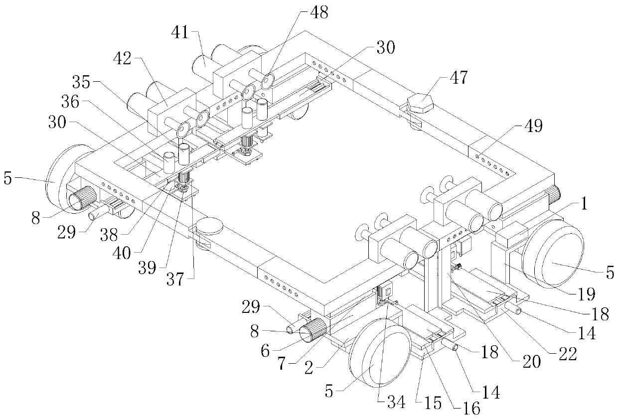
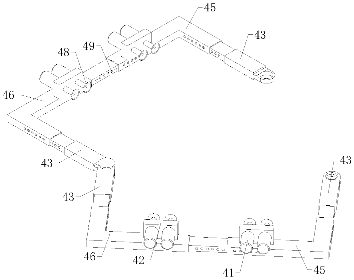
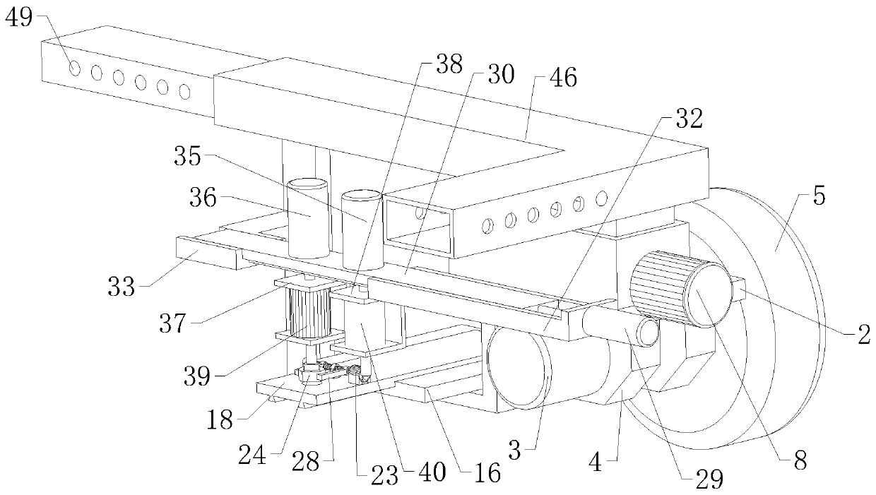
The invention relates to the technical field of power grids, and specifically relates to auxiliary equipment for the installation of a power distribution cabinet. The equipment comprises a bracket, four walking mechanisms, four clamping mechanisms and four mounting devices. The bracket is of a rectangular frame structure, and is horizontally arranged. The four clamping mechanisms are symmetricallyarranged at the middles of the top ends of a left side bracket and a right side bracket. The output ends of the clamping mechanism are oppositely arranged; the four mounting devices are symmetricallyarranged at the middles of the bottom ends of the left side bracket and the right side bracket respectively. According to the invention, the automatic transportation of the power distribution cabinet, punching, bolt installation and screw cap fastening can be achieved through the telescopic bracket and the walking mechanisms, clamping mechanisms and mounting devices arranged on the bracket. The equipment can greatly reduce the inaccuracy of manual installation, greatly improves the installation efficiency of the power distribution cabinet, and is high in speed. Moreover, the equipment is suitable for the installation of power distribution cabinets in different sizes, greatly saves the installation cost, and increases the construction speed.

Description

technical field [0001] The invention relates to the technical field of power grids, in particular to an auxiliary device for installing a power distribution cabinet. Background technique [0002] The power distribution cabinet (box) is divided into power distribution cabinet (box), lighting distribution cabinet (box), metering cabinet (box), and is the final equipment of the power distribution system. When installing the power distribution cabinet, it is necessary to manually drill holes on the ground, then align the installation holes on the bottom plate of the power distribution cabinet with the holes already drilled on the ground, and then place expansion bolts and tighten them. This method cannot guarantee The holes on the ground are aligned with the holes on the bottom plate of the power distribution cabinet. At the same time, this method is inefficient, slow, and high in cost. However, the installation auxiliary equipment of the traditional power distribution cabinet i...

Claims


Application Information

Patent Timeline
IPC IPC(8): H02B3/00
Inventor 徐小梅
Owner 徐小梅
Learn More