Integrated mechanical arm taking-out plate

A manipulator, one-piece technology, applied in the field of one-piece manipulator taking out plates, can solve the problems of poor stability of the manipulator, heavy take-out plate weight, large load, etc., and achieve the effects of convenient processing, weight reduction, and load reduction.

Inactive Publication Date: 2019-06-28
DEMARK (CHANGXING) INJECTION SYST CO LTD
View PDF1 Cites 0 Cited by
  • Summary
  • Abstract
  • Description
  • Claims
  • Application Information

AI Technical Summary

Problems solved by technology

[0005] The purpose of the present invention is to address the deficiencies of the prior art and provide an integrated manipulator to take out the board. By processing an independent board to include a main board part and a sub-board part, a branch channel is opened on the main board part, and A main channel is set at the junction of the main board part and the sub-board part, and the branch channel and the main channel are directly drilled and connected, thereby solving the problem of the heavy weight of the existing embryo taking manipulator, especially when dealing with multi-cavity manipulators. The problem of poor stability when the load is large and the manipulator is working

Method used


Image

  • Integrated mechanical arm taking-out plate
  • Integrated mechanical arm taking-out plate
  • Integrated mechanical arm taking-out plate

Examples


Embodiment 1

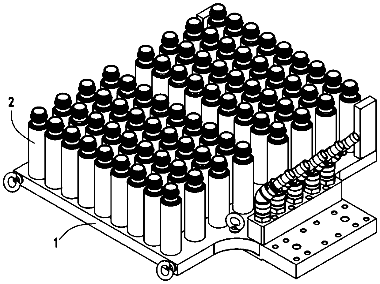
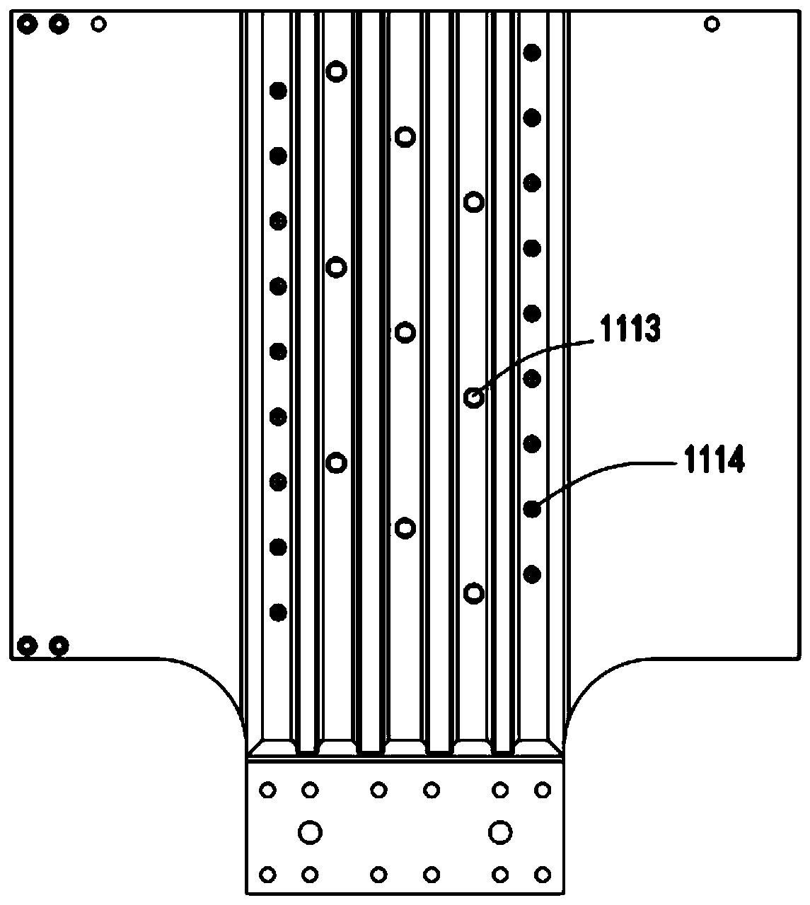
[0035] Such as Figure 1 to Figure 6 As shown, an integrated manipulator takes out the plate, including a bottom plate 1, and the bottom plate 1 includes a main board part 11 and a sub-board part 12. The branch channel 111 communicates with the main channel 121 opened at the junction of the main board part 11 and the sub-board part 12 .

[0036] It is worth mentioning that by processing an independent board to include the main board part 11 and the sub-board part 12, a branch channel 111 is opened on the main board part 11, and a branch channel 111 is opened at the junction of the main board part 11 and the sub-board part 12. The main flow channel 121, compared with the existing way of combining two plates, greatly reduces the weight of the embryo taking manipulator to take out the plate, especially when dealing with multi-cavity manipulators, it reduces the load of the manipulator cantilever and improves the manipulator. job stability

[0037] Further, the thickness of the ...

Embodiment 2

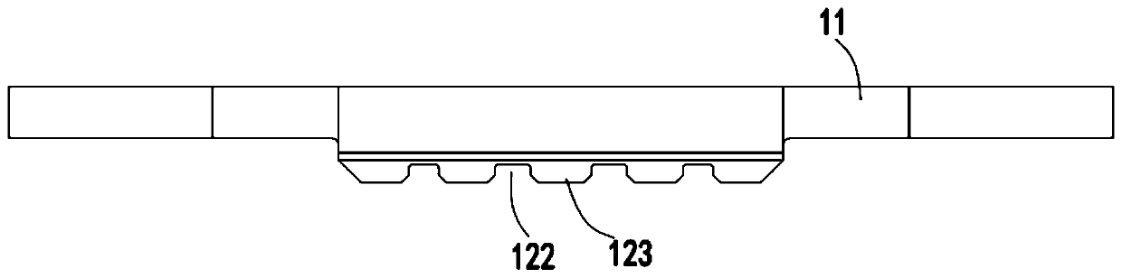
[0048] Such as figure 2 As shown, the components that are the same as or corresponding to those in the first embodiment are marked with the corresponding reference numerals in the first embodiment. For the sake of simplicity, only the differences from the first embodiment will be described below. The difference between the second embodiment and the first embodiment is that: the surface of the sub-plate part 12 is provided with a groove 122 between two adjacent main channels 121, and a protrusion is formed between two adjacent grooves 122 part 123 , the main flow channel 121 is set at the middle position in the width direction of the raised part 123 .

[0049] It should be pointed out that by opening a groove 122 between two adjacent main channels 121 on the surface of the sub-plate part 12, it further reduces the weight of the taken-out plate without affecting the structural strength, and improves the operation efficiency of the manipulator. stability.


PUM


Abstract

The invention relates to an integrated mechanical arm taking-out plate. The integrated mechanical arm taking-out plate comprises a bottom plate, wherein the bottom plate comprises a main plate part and an auxiliary plate part, the main plate part and the auxiliary plate part are integrally arranged, and a branch flow channel formed in the main plate part is in communication with a main flow channel formed in the joint position between the main plate part and the auxiliary plate part. According to the integrated mechanical arm taking-out plate, the problems that a taking-out plate of an existing blank taking mechanical arm is large in weight, especially the load of a mechanical arm cantilever is large for the mechanical arm with multiple cavities and the stability of the mechanical arm is poor in the working process of the mechanical arm can be solved.

Description

technical field [0001] The present invention relates to the technical field of preform fetching manipulators of preform forming equipment, and in particular to an integrated manipulator taking out plates. Background technique [0002] The preform injection molding machine is mainly composed of an injection molding machine and a multi-cavity mold. It is mainly used to produce plastic preforms. The injected preforms are further blow-molded to obtain products such as plastic bottles or medical packs. During the production of the preform injection molding machine, the manipulator is required to take out the formed preform and cool the preform. [0003] A Chinese utility model patent with a publication number of CN201020841 discloses a water-cooled embryo taking robot combination device, which includes three parts: translation, rotation, and embryo transfer cooling device, the rotation device; the rotation device and the embryo transfer cooling device It can move horizontally wi...

Claims


Application Information

Patent Timeline
Patent Type & Authority Applications(China)
IPC IPC(8): B29C45/42
Inventor 史克涛王巍植符余朝沈吉徐金鑫
Owner DEMARK (CHANGXING) INJECTION SYST CO LTD
Why Eureka
Try Eureka