High-frequency shifting fork quenching device

A quenching device and high-frequency quenching technology, which are applied in the direction of quenching devices, energy efficiency, process efficiency, etc., can solve the problems of difficult control of metal workpieces, low yield rate of metal quenching treatment, difficult quenching processing at the quenching position, etc. To achieve the effect of easy access

Pending Publication Date: 2019-06-28
LAIZHOU JINHONG CNC EQUIP CO LTD
View PDF0 Cites 2 Cited by
  • Summary
  • Abstract
  • Description
  • Claims
  • Application Information

AI Technical Summary

Problems solved by technology

[0003] At present, the domestic industry generally adopts manual high-frequency quenching, or non-professional semi-automatic numerical control high-frequency quenching, which mainly uses manual induction heating and quenching of metal workpieces one by one on the quenching machine, or quickly Immersed in a water pool (oil pool) for cooling, due to manual operation, it is impossible to control the continuity of rapid heating of metal workpieces, it is difficult to control the size of the quenching hardness transition zone of metal workpieces, and it is also difficult to ensure the internal distribution of the hardened layer and the high frequency Uniformity of quenching hardness, resulting in low yield and poor effect of metal quenching treatment
[0004] The shift fork is an irregular part, and the quenching part is the part in contact with the gear sleeve of the synchronizer. It is also difficult to perform quenching at the quenching position. At present, most of the fully automatic high-frequency quenching machines transfer the workpiece to be quenched to the designated place through the conveyor belt. The processing position uses a clamping device to quench the workpiece to be quenched, but the quenching device intelligently realizes the quenching of regular objects. For irregular processed parts such as shift forks, it is difficult to achieve fixed-point transmission and clamping of the workpiece by the conveyor belt. How to Realizing automatic quenching of irregular workpieces is a problem that needs to be solved at this stage

Method used


Image

  • High-frequency shifting fork quenching device
  • High-frequency shifting fork quenching device
  • High-frequency shifting fork quenching device

Examples


Embodiment 1

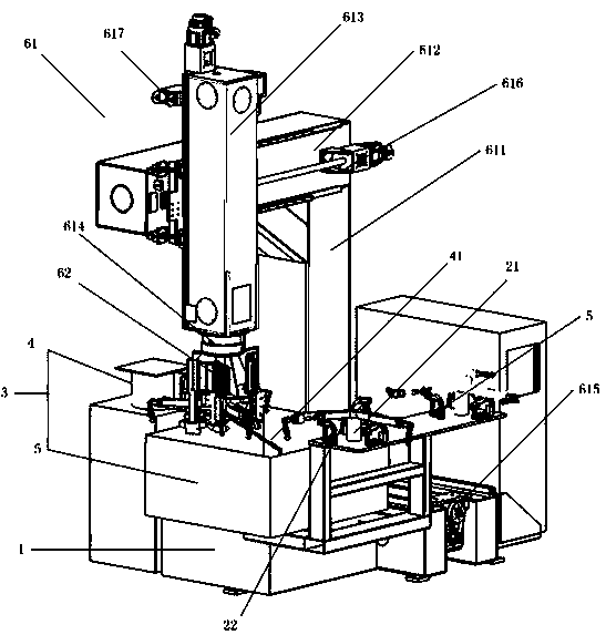
[0033] Such as Figure 1-5 The present invention discloses a high-frequency fork quenching device, the high-frequency fork quenching device includes a base 1, a high-frequency quenching device 4 and control equipment,

[0034] The base 1 is provided with a fork placement table 2 and a high-frequency quenching work area 3;

[0035] The high-frequency quenching working area 3 is provided with a high-frequency quenching device 4 and a pool 5, the high-frequency quenching device 4 is provided with a quenching rod 41, and the end of the quenching rod 41 extends into the pool 5;

[0036] The shift fork placement table 2 is provided with a plurality of placement slots 21, the placement slots 21 are placed with a shift fork carrier 22, and the shift fork carrier 22 is equipped with at least two shift forks. The shift fork carrier 22 moves to the high frequency quenching work area 3 through the shift fork moving device;

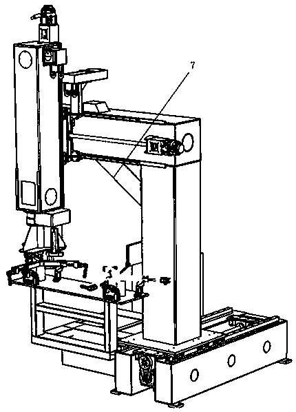
[0037] The shift fork moving device includes a four-axis linka...

Embodiment 2

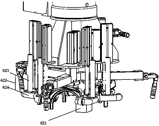
[0045] The specific operation of the clamping and placement of the shift fork is to put the top end of the OEM shift fork into the front pin of the load arm, operate the piston rod in the short arm of the locking frame body, move the piston rod to offset the shift fork, and press the lock body Press down to tighten the position of the piston rod, and then adjust the adjustable screw to further clamp the processing fork, so that the fork is tightly assembled on the fork carrier. After the fork carrier is fully loaded with the fork, put the Put the fixed column on the shift fork carrier into the placement slot, abut one section of the shift fork against the horizontal positioning block to realize the lateral positioning of the shift fork, and then fit the other end of the shift fork to the angle image of the longitudinal positioning block to complete the shifting fork Longitudinal positioning to realize the clamping placement of the shift fork.

Embodiment 3

[0047] During the specific operation, the X moving axis in the shift fork moving device slides through the X-axis motion guide rail, moves the feeding manipulator to be level with the placement table, and then starts the Y moving axis to make the Z moving axis slide on the Y-axis motion guide rail. The feeding manipulator moves to the top of the shift fork carrier to be clamped, starts the Z moving axis, makes the Z moving axis move relative to the Y moving axis through the Z-axis motion guide rail, moves up and down along the Z-axis direction, and lowers the feeding manipulator to the carrier frame Level, start the fixed block of the carrier frame, the cylinder pushes the fixed block of the carrier frame down until the fixed block of the carrier frame is lower than the fork carrier frame, start the rotary feeding manipulator of the A rotation axis, rotate the fixed block of the carrier frame to the right below the carrier frame, and the cylinder Drive the fixed block of the be...


PUM


Abstract

The invention discloses a high-frequency shifting fork quenching device. The high-frequency shifting fork quenching device comprises a base, a high-frequency quenching device body and control equipment, wherein a shifting fork storage table and a high-frequency quenching working area are arranged on the base; a plurality of storage grooves are formed in the shifting fork storage table; a shiftingfork loading frame is placed on the storage grooves; a shifting fork moving device comprises a four-shaft linkage displacement device and a feeding manipulator; the feeding manipulator is fixedly connected with the four-shaft linkage displacement device; and the feeding manipulator comprises a loading frame fixing block and a quenching cooling device. Workpieces placed at different positions can be clamped and moved more flexibly through four-axis linkage compared with fixed-point conveying of a conveying belt, and the device can be adapted to various working environments; irregular workpiecescan be placed reasonably by using the loading frame; and multiple workpieces can be clamped by the loading frame at one time, and then the loading frame is rotated by four-shaft linkage machining grips for machining, so that the machining is more flexible and simple, and the working efficiency is improved.

Description

technical field [0001] The invention relates to the technical field of workpiece surface treatment, in particular to a high-frequency fork quenching device. Background technique [0002] The place where the shift fork is most prone to wear is the contact part between the shift fork and the synchronizer sleeve, because the synchronizer sleeve rotates at high speed but the shift fork does not rotate, the wear of the shift fork, or insufficient strength may cause the gear to not hang in place and fall off. The gear, or the shift fork is broken. In order to solve the above problems, the parts in contact with the shift fork and the synchronizer sleeve can be quenched and hardened at high temperature. [0003] At present, the domestic industry generally adopts manual high-frequency quenching, or non-professional semi-automatic numerical control high-frequency quenching, which mainly uses manual induction heating and quenching of metal workpieces one by one on the quenching machine...

Claims


Application Information

Patent Timeline
Patent Type & Authority Applications(China)
IPC IPC(8): C21D9/00C21D1/667C21D1/42
CPCY02P10/25
Inventor 王建军
Owner LAIZHOU JINHONG CNC EQUIP CO LTD
Why Eureka
Try Eureka