Pin fastening component

A technology for fastening components and pins, applied in the field of pin fastening components and formwork, can solve the problems that the pins are not easily inserted into the holes of the pins, affect the pouring quality of the concrete wall, and the pins and pin connections are easy to loosen, etc. The effect of convenient and quick disassembly, simple structure, stable and reliable structure

Pending Publication Date: 2019-06-28
赵永振
View PDF1 Cites 0 Cited by
  • Summary
  • Abstract
  • Description
  • Claims
  • Application Information

AI Technical Summary

Problems solved by technology

[0005] 1. The template is easy to deform and expand the mold
[0006] The pin is inserted into the hole of the pin to achieve the purpose of connecting two templates. This connection structure is basically "point" contact, the clamping area is small, the mold is easy to expand when dusting, and the service life is low; the template is easy to deform, directly Affects the pouring quality of concrete walls
[0007] 2. Difficult to install
[0008] The pins and pins are plugged in. Due to the unequal gap between the two templates, it is difficult for the pins to be inserted into the holes of the pins.
[0009] 3. Pins and pins are easy to loosen
[0010] Due to the use of vibrating rods during the grouting process, when the pins are vibrated and the two sides of the pins are inclined structures, the pins are easy to move and fall out. At this time, the pins and pins basically do not play the role of clamping , prone to bulge and dust
[0011] 4. The connection between the pin and the pin is not tight and easy to loosen
[0012] The pin is basically very easy to use for the first time. When the pin is inserted into the pin hole and hammered vigorously, there are often "steps" on the edge where the pin contacts the pin. When the pin is used for the second time, the pin will be stuck on this The "step" position, causing the problem of pin not tight

Method used


Image

  • Pin fastening component
  • Pin fastening component
  • Pin fastening component

Examples


no. 1 example

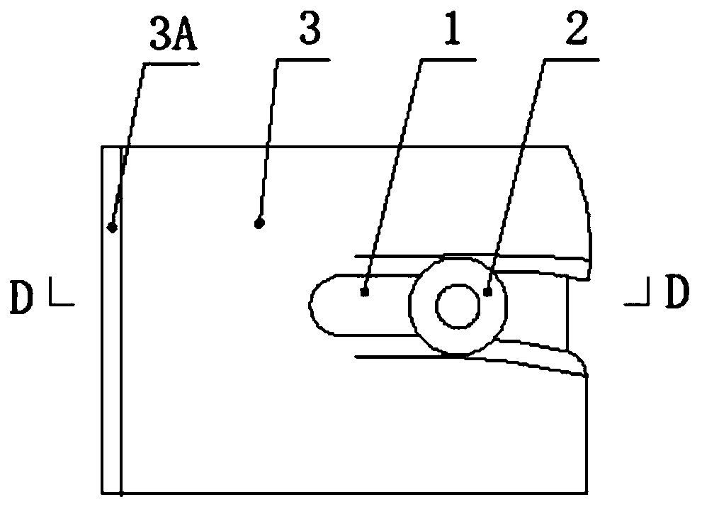
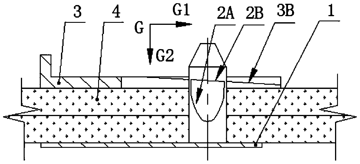
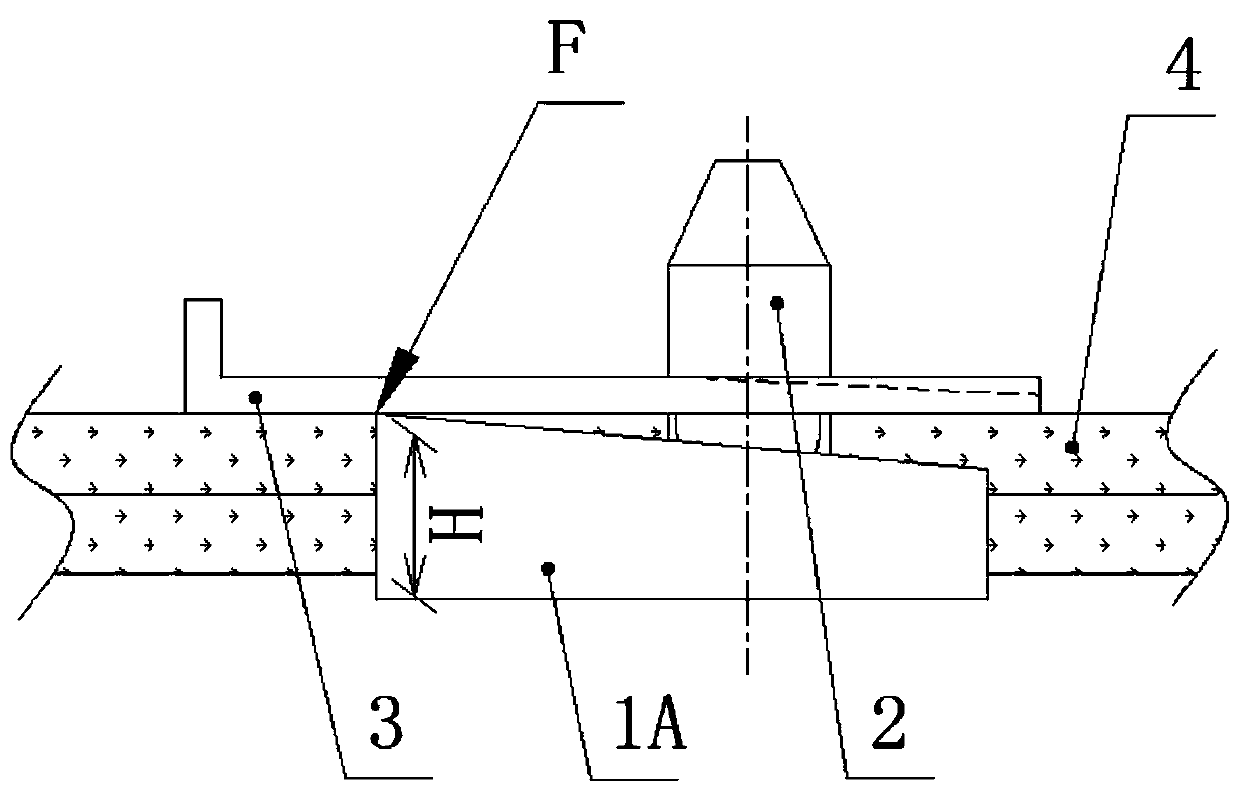
[0046] A pin fastening member such as Figure 1 to Figure 3 As shown, it includes a pin 2 and a pin piece 3, the inner end of the pin is fixed on the splint 1, and one side of the pin piece is formed with a draw-in groove 3A for accommodating the pin, as Figure 4 shown.

[0047] The specific structure of the pin is as follows:

[0048] 2. The outer edge of the pin is symmetrically formed with a first clamping slope 2A along the axial direction, such as image 3 As shown, the inclination angle β between the first clamping slope and the axis of the pin is 10-25 degrees, the first clamping slope corresponds to the second clamping slope 2B formed on the outer edge of the pin, and the second clamping The inclination angle α of the slope is 3-10 degrees. In order to facilitate the pins to be inserted into the formwork holes and the slots of the pins during installation, the pins have a truncated cone structure or the outer end of the pins has a truncated cone structure.

[0049...

no. 2 example

[0057] On the basis of the above-mentioned first embodiment, two parts of the screw rod 6 and the threaded sleeve 5 are added, specifically as Figure 6 , Figure 7 As shown, a screw rod is fixedly installed on the pin sheet corresponding to the side of the pin sheet slot, and the screw rod is threadedly connected in the threaded sleeve fixed on the splint. The card slot is an arc structure.

[0058] The tail portion of the pin piece is an arc structure, which is exquisite in structure, easy to use, strong in practicability, and durable in purpose.

[0059] Through the setting of the screw and the threaded sleeve, it not only has the advantages of the pin piece rotating around the screw rod, increasing the positioning point, and preventing the screw from falling out, but more importantly, the process of the pin piece and the pin being matched through the thread cooperation between the screw rod and the threaded sleeve The purpose of clamping gradually, and finally clamping the...

no. 3 example

[0062] Such as Figure 8 As shown, on the basis of the second embodiment, the splint is lengthened, and a group of pins and pin pieces are added. Two groups of pins and pin sheets are installed on the splint, and the two groups of pins and pin sheets are arranged at intervals up and down.

[0063] Through the design of conjoined pins and pins, its acceptance is larger and stronger, and it is suitable for independent columns, stairs, wall formwork, and any position where there is no way to set pull tabs and back corrugations.


PUM


Abstract

The invention relates to a pin fastening component. The pin fastening component comprises a pin and a pin sheet, wherein the inner end part of the pin is fixedly arranged on a clamping plate; one sideof the pin sheet is provided with a clamping groove for accommodating the pin; the outer edge of the pin is symmetrically provided with a first clamping inclined plane along the axial direction; theinclination angle between the first clamping inclined plane and the axis of the pin is beta; the first clamping inclined plane is in contact with a second clamping inclined plane arranged on the outeredge of the pin; the inclination angle of the second clamping inclined plane is alpha; two side edges of one end surface of the clamping groove of the pin sheet are provided with a pin sheet inclinedplane matched with the second clamping inclined planes; and the inclination angle of the pin sheet inclined plane is gamma. According to the pin fastening component, two clamping inclined planes arearranged on the outer edge of the pin, and are matched with the clamping groove of the pin sheet and the pin sheet inclined plane, so that the deeper the pin sheet is inserted, the closer the pin sheet is matched with a clamping piece. The pin fastening component adopts a double progressive clamping mode, namely, on the one hand the pin and the pin sheet are matched and clamped, and on the other hand, a screw rod and a threaded sleeve are matched and clamped, so that the two templates are firmly jointed and clamped.

Description

technical field [0001] The invention belongs to the technical field of building construction and relates to a formwork, in particular to a pin fastening component. Background technique [0002] Building formwork is composed of panels and support systems. The quality of formwork assembly is related to the quality of concrete engineering. The key lies in accurate size, firm assembly, tight joints, and convenient disassembly and assembly. At present, pins and pin sheets are usually used as connecting fasteners of the formwork. [0003] After searching, a patent document similar to this patent application was found, the name is: a template connector, and the application publication number is: CN106121229A. The published content of this patent application is: including a pin, a pin piece and a connecting rope connecting the pin and the pin piece; The body is provided with a pin hole, and one side of the nail cap has a protrusion. [0004] By comparison, it is found that the ab...

Claims


Application Information

Patent Timeline
Patent Type & Authority Applications(China)
IPC IPC(8): E04G17/00E04G17/075
Inventor 赵永振
Owner 赵永振
Why Eureka
Try Eureka