Loop heat pipe type heating and refrigerating air conditioning system

An air-conditioning system, loop heat pipe technology, applied in the direction of air-conditioning systems, refrigerators, heating methods, etc., can solve the problem of high resistance of the refrigerant along the way, to improve the heating or cooling effect, improve stability, and reduce resistance Effect

Pending Publication Date: 2019-06-28
四川长虹空调有限公司
View PDF0 Cites 5 Cited by
  • Summary
  • Abstract
  • Description
  • Claims
  • Application Information

AI Technical Summary

Problems solved by technology

[0004] The present invention aims to solve the problem of high resistance of the refrigerant along the path of the existing loop heat pipe air conditioning system, and proposes a loop heat pipe heating and cooling air conditioning system

Method used


Image

  • Loop heat pipe type heating and refrigerating air conditioning system
  • Loop heat pipe type heating and refrigerating air conditioning system
  • Loop heat pipe type heating and refrigerating air conditioning system

Examples


Embodiment 1

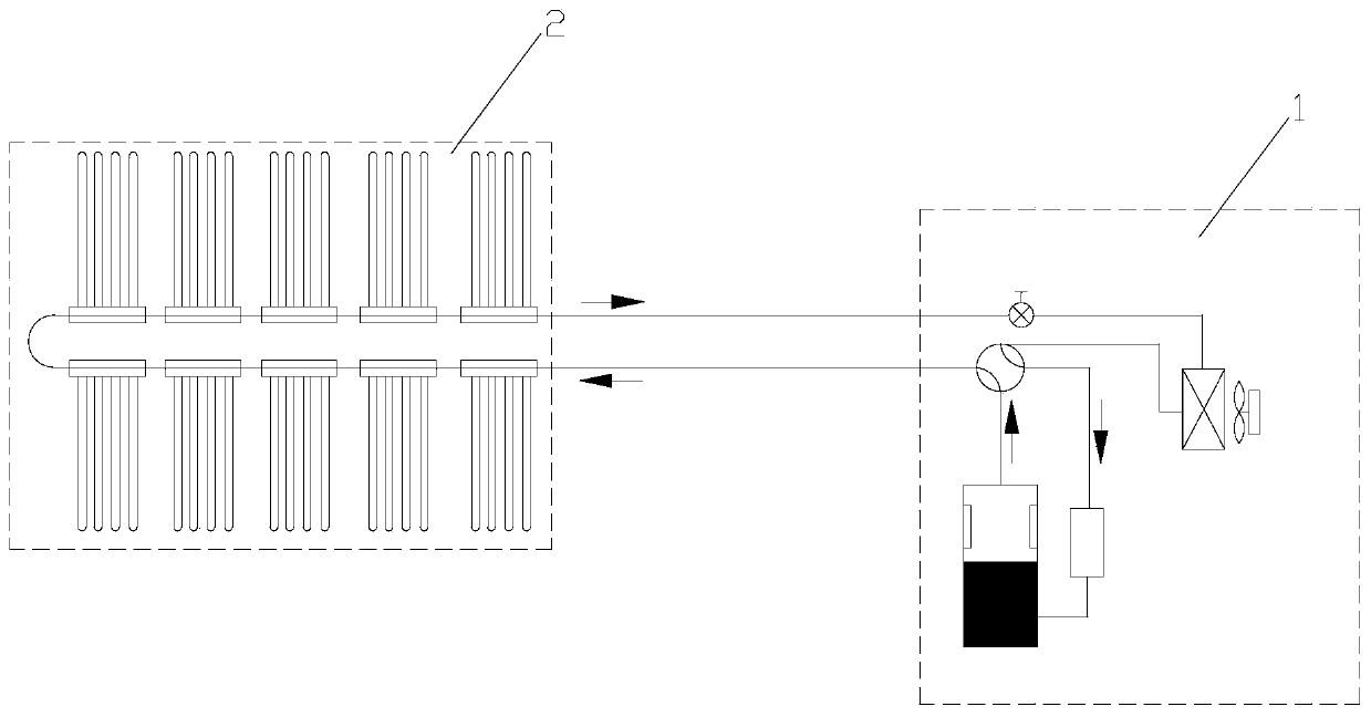
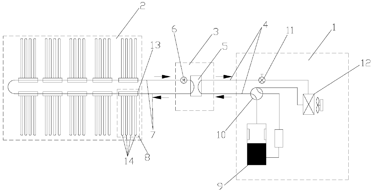
[0060] This example illustrates the loop heat pipe heating and air-conditioning system as an example. image 3 As shown, the loop heat pipe heating and air conditioning system described in this embodiment includes: a heating cycle unit 1, a loop heat pipe unit 2 and an intermediate heat exchange unit 3, and the heating cycle unit 1 has a first refrigerant, the loop heat pipe unit 2 has a second refrigerant;

[0061] The heating cycle unit 1 is used to form a heating cycle of the first refrigerant;

[0062] The loop heat pipe unit 2 is used to condense and release heat after the second refrigerant absorbs heat;

[0063] The intermediate heat exchange unit 3 is used for refrigerant heat exchange between the first refrigerant in the heating cycle unit 1 and the second refrigerant in the loop heat pipe unit 2 .

[0064] Among them, the heating cycle unit 1 is connected to the loop heat pipe unit 2 through the intermediate heat exchange unit 3, the heating cycle unit 1 forms a he...

Embodiment 2

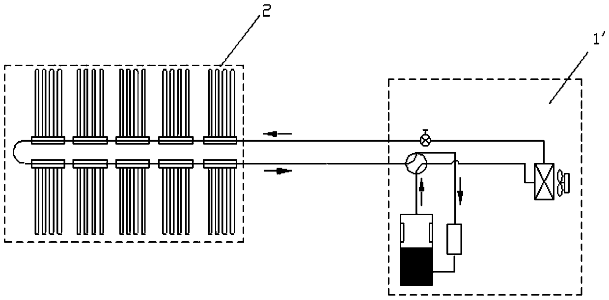
[0088] In this embodiment, the loop heat pipe refrigeration and air-conditioning system is illustrated with an example, such as Figure 8 As shown, the loop heat pipe refrigeration and air-conditioning system described in this embodiment includes: a refrigeration cycle unit 1 ′, a loop heat pipe unit 2 and an intermediate heat exchange unit 3 , and the refrigeration cycle unit 1 ′ has a first Refrigerant, the loop heat pipe unit 2 has a second refrigerant;

[0089] The refrigeration cycle unit 1' is used to form a refrigeration cycle of the first refrigerant;

[0090] The loop heat pipe unit 2 is used for evaporating and absorbing heat after the second refrigerant is condensed;

[0091] The intermediate heat exchange unit 3 is used for heat exchange between the first refrigerant in the refrigeration cycle unit 1 ′ and the second refrigerant in the loop heat pipe unit 2 .

[0092] In this embodiment, the refrigeration cycle unit 1' is connected to the loop heat pipe unit 2 th...


PUM


Abstract

The invention relates to the technical field of air conditioners, aims to solve the problem of large on-way resistance of a refrigerant of an existing loop heat pipe type air conditioning system and provides a loop heat pipe type heating and refrigerating air conditioning system. The loop heat pipe type heating and refrigerating air conditioning system comprises at least one heating or refrigerating cycle unit, at least one loop heat pipe unit and at least one intermediate heat exchange unit, wherein the intermediate heat exchange unit is used for refrigerant heat exchange between the heatingor refrigerating cycle unit and the loop heat pipe unit. The heating or refrigerating cycle heat generated by the air conditioning system is transferred to the loop heat pipe unit through the intermediate heat exchange unit, and the loop heat pipe unit heats or cools the indoor space, so that the length of a refrigerant pipeline of the heating or refrigerating cycle unit of the air conditioning system is reduced, the resistance of a refrigerant flow is reduced, and the heating or refrigerating effect of the loop heat pipe type air conditioning system is improved. The loop heat pipe type heating and refrigerating air conditioning system is suitable for a floor heating system.

Description

technical field [0001] The invention relates to the technical field of air conditioning, in particular to a loop heat pipe heating and cooling air conditioning system. Background technique [0002] As a kind of household indoor temperature control system, the air conditioner has been popularized in consumers' families. The split type air conditioner includes an indoor unit and an outdoor unit. In the existing indoor units of an air conditioner, cold or hot air is blown out through the air outlet to provide cooling or heat to the room. When the air outlet blows out, the wind blows on the user, which will bring the user uncomfortable feeling and affect the user's experience. And the convective heat transfer will cause obvious temperature gradient and uneven temperature distribution in the indoor temperature. [0003] The existing main technical solution to solve the uneven distribution of indoor temperature field and the uncomfortable feeling of blowing is to conduct heat ex...

Claims


Application Information

Patent Timeline
Patent Type & Authority Applications(China)
IPC IPC(8): F25B13/00F25B41/00F28D15/02F24F1/0003F25B41/40
Inventor 李越峰杨涛袁竹赵坤
Owner 四川长虹空调有限公司
Why Eureka
Try Eureka