Multifunctional machine vision experimental platform
A machine vision and experimental platform technology, applied in the field of inspection, can solve the problems of inability to implement line scan cameras, reduced efficiency, slow speed, etc., and achieves the effects of fast inspection speed, improved efficiency, and convenient production.
- Summary
- Abstract
- Description
- Claims
- Application Information
AI Technical Summary
Problems solved by technology
Method used
Image

Examples
Embodiment 1
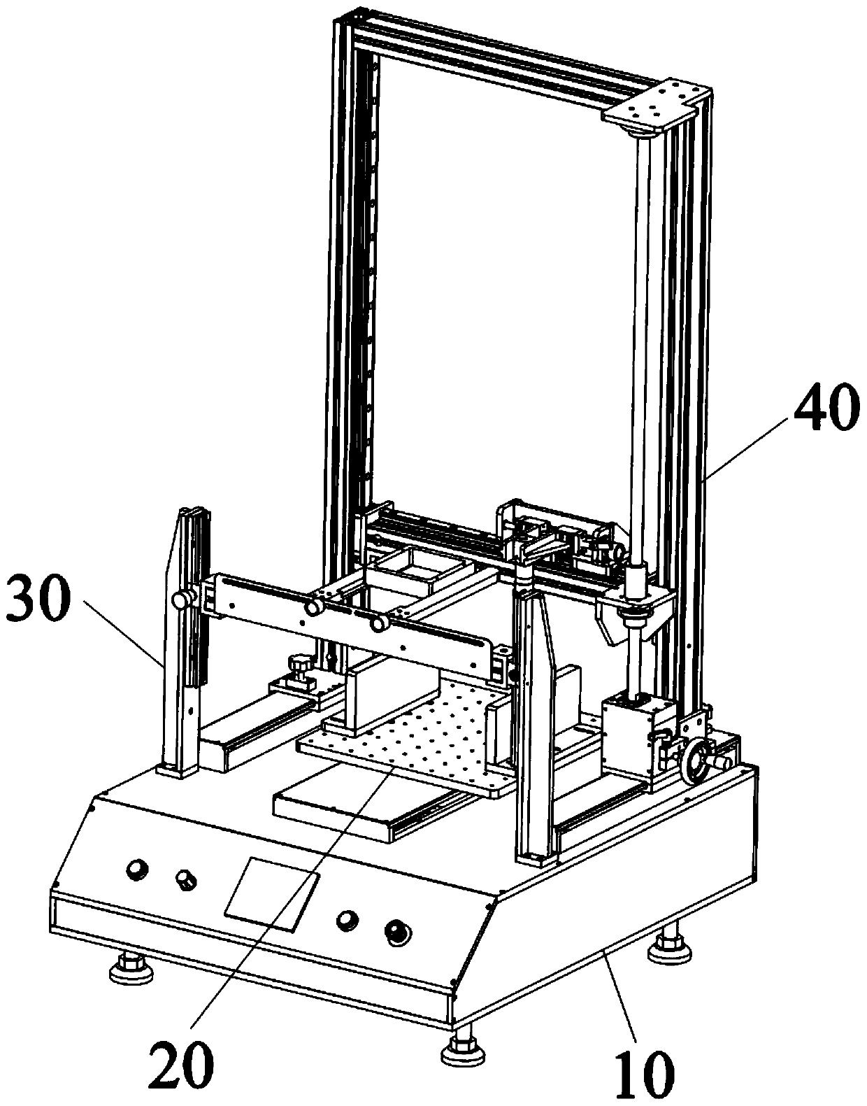
[0031] see Figure 1 to Figure 4 As shown, the present embodiment provides a multifunctional machine vision experiment platform, including a machine platform 10, on which an object conveying device 20, a light source device 30 and a line-scanning camera device 40 are fixedly arranged, and the light source device 30 and a line-scanning camera device 40 are fixedly arranged on the machine platform 10. The camera devices 40 are respectively located on two sides of the object conveying device 20 .
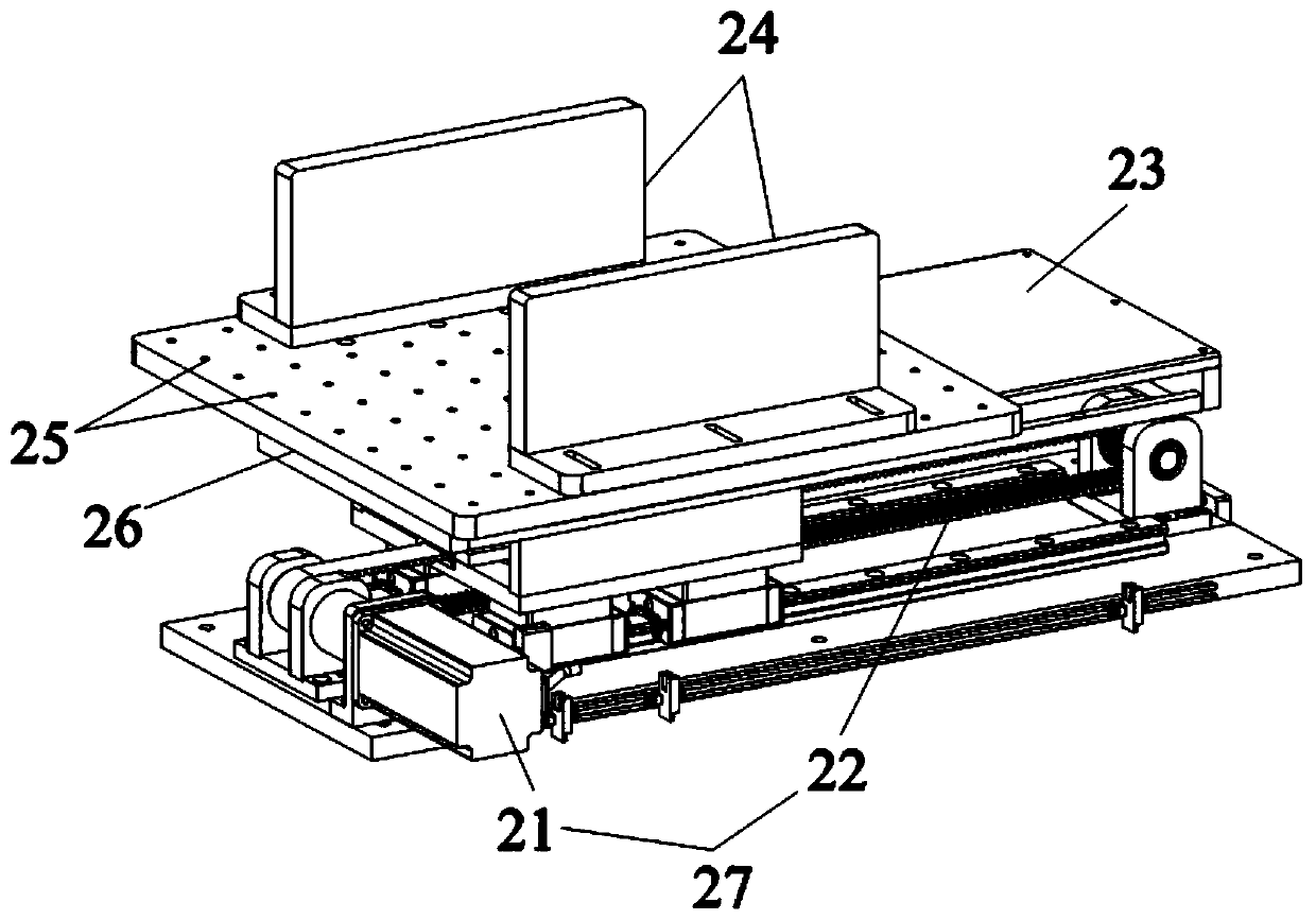
[0032] The object conveying device 20 includes a conveying mechanism 27, on which a platform plate 26 for placing objects is drivingly connected, and both sides of the platform plate 26 are respectively equipped with clamping blocks 24 for clamping objects. Clamping blocks 24 are used to secure objects to platform deck 26 .
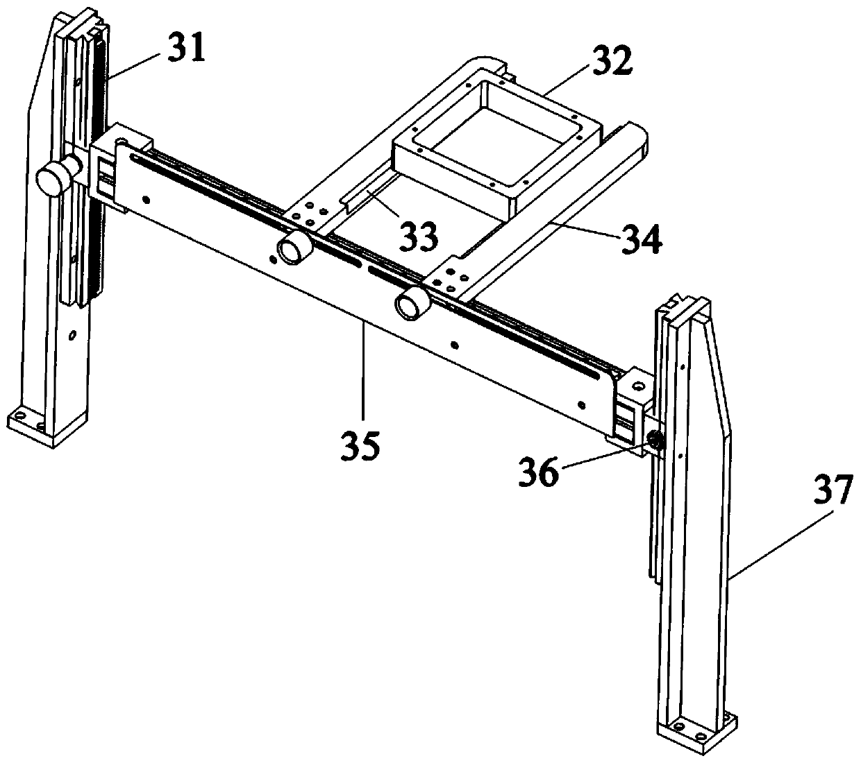
[0033] The light source device 30 includes a liftable sliding table module, on which a light source clamping assembly is fixedly installed, and the height of the...
Embodiment 2
[0038] On the basis of the first embodiment, the platform board 26 is provided with a plurality of fixing holes 25 , and the clamping block 24 is fixed on the fixing holes 25 through fixing pieces, and the plurality of fixing holes 25 are distributed in a grid shape. Objects of different sizes can be fixed by utilizing the grid-shaped fixing holes 25 . Specifically, the clamping blocks 24 are fixed on different fixing holes 25 by moving and adjusting, so as to adjust the distance between the two clamping blocks 24 . As an optional way to adjust the distance, one of the clamping blocks 24 remains still, and the other clamping block 24 changes its fixed position.
Embodiment 3
[0040] On the basis of the first or second embodiment, the transmission mechanism 27 includes a motor 21 and a synchronous belt 22 , and the motor 21 is connected to the synchronous belt 22 by driving. This embodiment specifically discloses a composition structure of the transmission mechanism 27 .
PUM
 Abstract
Description
Claims
Application Information