
Power measurement and radio frequency receiving gain control method applied to channel simulator

A technology of power measurement and channel simulation, applied in receiver monitoring, transmission monitoring, electrical components and other directions, it can solve the problems of complex algorithm, inability to distinguish signal input power, large calibration workload, etc., to achieve small switching delay and calibration process. Simple and fast, simple power measurement algorithm effect

Active Publication Date: 2019-06-28
SOUTHEAST UNIV +1
View PDF6 Cites 3 Cited by
  • Summary
  • Abstract
  • Description
  • Claims
  • Application Information

AI Technical Summary

Problems solved by technology

[0007] In view of the deficiencies of the above-mentioned prior art, the purpose of the present invention is to solve the problem that the channel simulator in the prior art uses automatic level control with an analog attenuator as the power distribution scheme of the receiving channel, which cannot distinguish the signal input power, and there is nonlinearity Influence, complex algorithm, heavy calibration workload

Method used

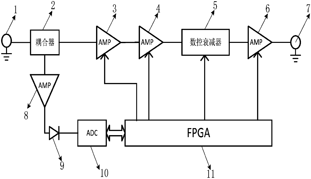
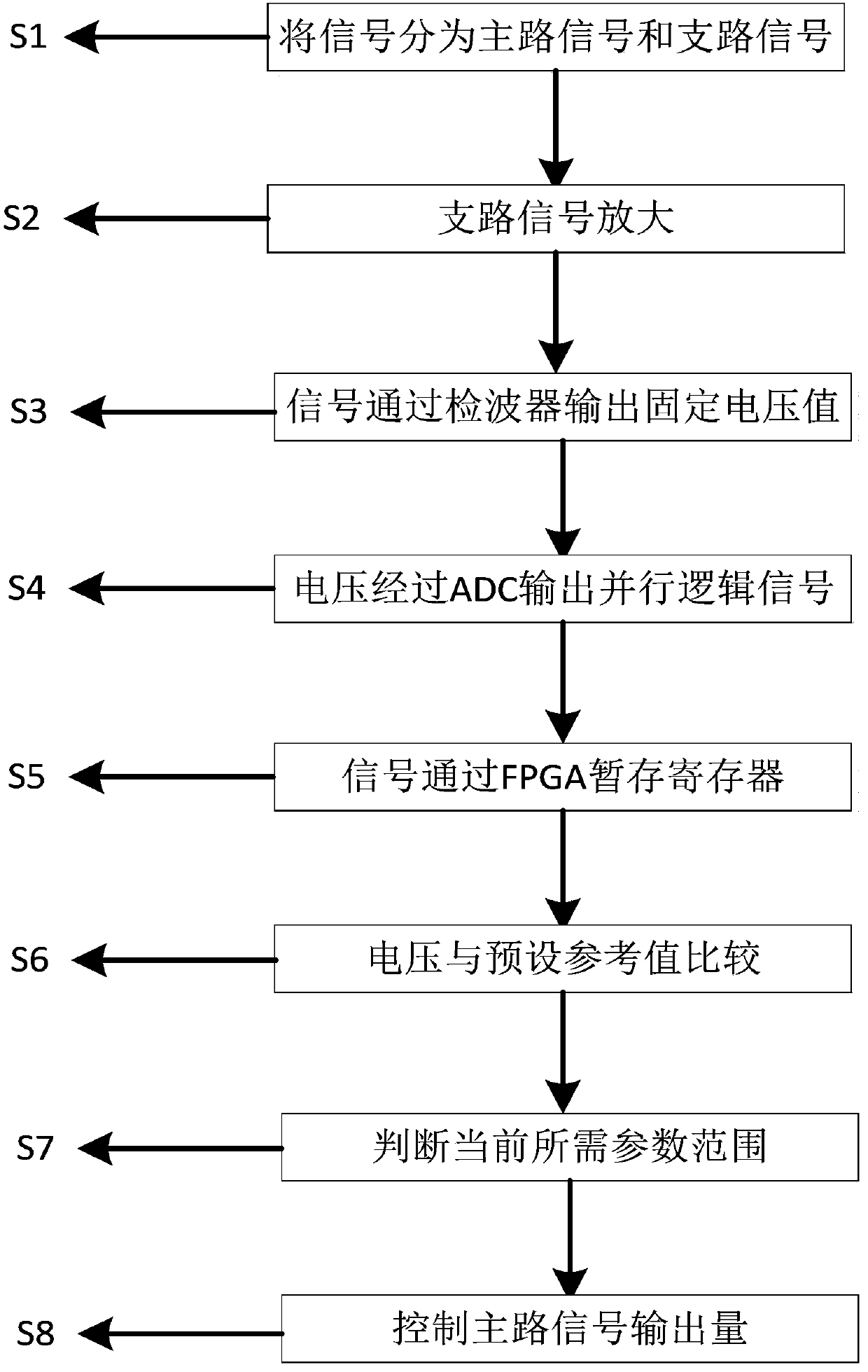
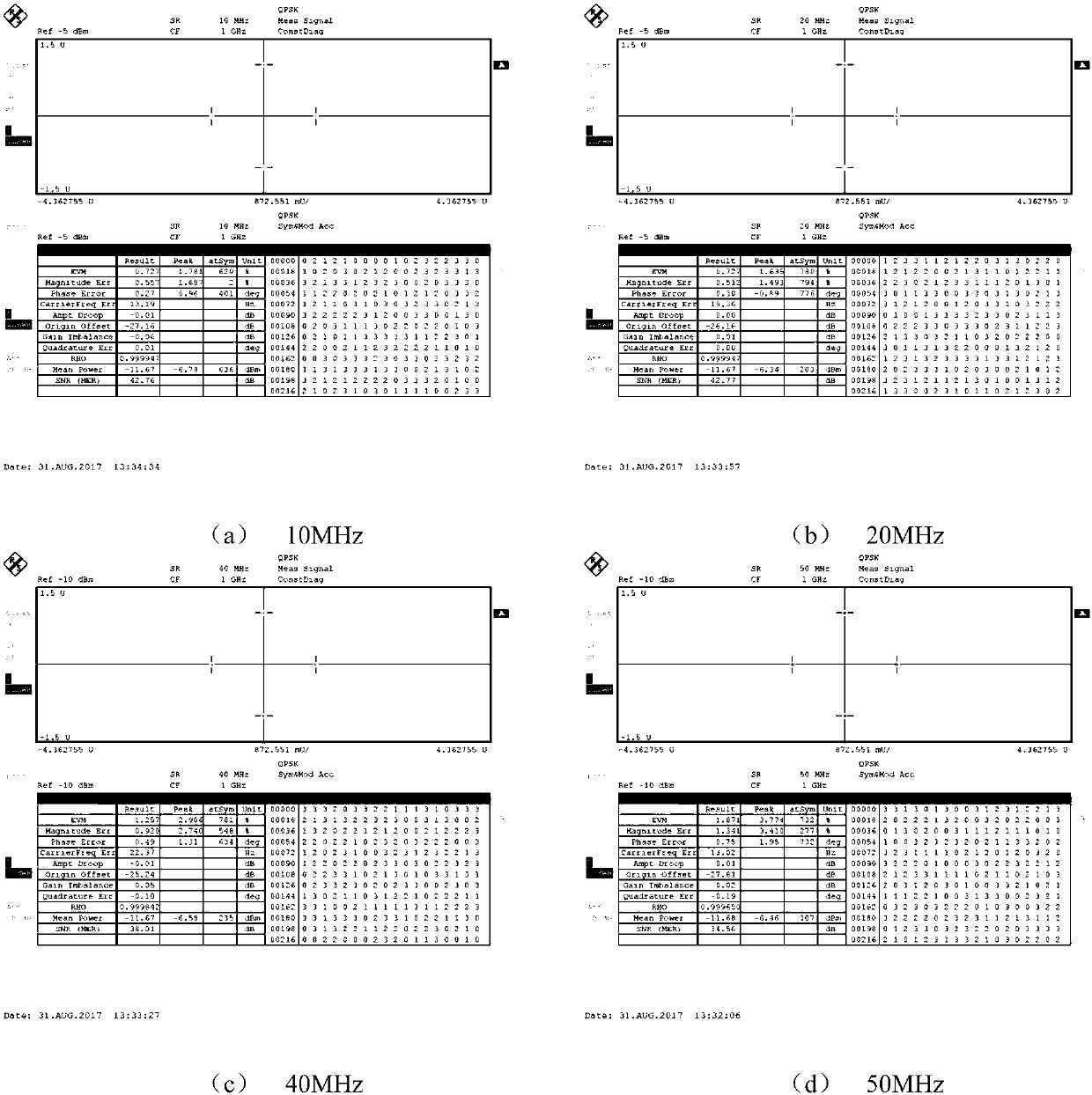

Image

  • Power measurement and radio frequency receiving gain control method applied to channel simulator
  • Power measurement and radio frequency receiving gain control method applied to channel simulator
  • Power measurement and radio frequency receiving gain control method applied to channel simulator

Examples


Embodiment

[0054] Although the method of this application supports a wide range of radio frequencies of 0.4-6GHz, the implementation process of each frequency point is the same, and the circuit verification is performed with 1GHz as a typical frequency point. The verification process is as follows:

[0055] 1. Verification of the output power of the input terminal 1 and output terminal 7

[0056] Input different power values ​​at the input terminal, according to the design plan, switch the on-off of the amplifier in the channel, and the value of the digital control attenuator 5, and test the output power of the output terminal 7, as shown in the table below.

[0057]

[0058] It can be seen from the table that the output power of the output terminal 7 is basically in the range of -20 ~ -15dBm, and only -60dBm input requires a slight adjustment of the digital control attenuator to meet the design requirements.

[0059] 2. Vector performance test of the external demodulator in the main ...


PUM


Abstract

The invention discloses a power measurement and radio frequency receiving gain control device applied to a channel simulator. The power measurement and radio frequency receiving gain control device comprises an input end, a coupler, a main signal branch, a branch signal branch and an output end. According to the invention, the nonlinear problem introduced by the channel simulator receiving channelsimulation device is solved, receiver vector performance is improved, and the algorithm problem of realizing power control in a digital domain is solved. Data are compared and analyzed in a digital domain, power distribution of a receiving channel is achieved, the problem that a channel simulator cannot automatically identify power of an input signal is solved. The problem that the channel simulator accurately measures the power of the input signal is solved, switching time delay is small, normal communication is not affected, a power measurement algorithm is simple, and the calibration process is simple and rapid.

Description

technical field [0001] The invention relates to the field of instrumentation, in particular to a power measurement and radio frequency receiving gain control method applied to a channel simulator. Background technique [0002] With the evolution of MIMO technology, wireless communication has become more and more complex. Wireless channels have unfavorable factors such as multipath fading and noise that affect communication performance. These unfavorable factors are issues that must be considered in communication system research. Channel simulation The device has a good approximate simulation effect on the wireless channel, which can greatly shorten the R&D cycle and reduce the test of the base station and terminal field. With the application of large-scale multi-antenna and high-frequency technology, 5G channel simulation will become 5G base station and terminal test. important tool. [0003] In the channel simulator system, it mainly includes the main control module, baseb...

Claims


Application Information

Patent Timeline
Patent Type & Authority Applications(China)
IPC IPC(8): H04B17/391H04B17/20H04B17/309H04B17/29
CPCY02D30/70
Inventor 蒋政波解建红刘景鑫
Owner SOUTHEAST UNIV
Learn More