
Adjustable resistor, current ripple elimination circuit with application of adjustable resistor, and line voltage compensation circuit

A technology of line voltage compensation and current ripple, which is applied in the field of circuits, can solve problems such as the difficulty in accurately controlling the current ripple chip, the loss of current ripple elimination, etc., and achieve the elimination of low-end jitter problems, good input power linear adjustment rate, Avoid the effect of too low impedance

Pending Publication Date: 2019-06-28
SHANGHAI BRIGHT POWER SEMICONDUCTOR CO LTD
View PDF7 Cites 10 Cited by
  • Summary
  • Abstract
  • Description
  • Claims
  • Application Information

AI Technical Summary

Problems solved by technology

However, in this LED dimming control circuit, the detection resistor used to realize current detection is mostly a fixed value. In this design, when the dimming application is applied, because the resistance value of the detection resistor is fixed, when the dimming depth is very deep, especially When the dimming current is close to zero, the voltage on the detection resistor is very small, and it is difficult to control the current ripple inside the chip accurately, and the function of eliminating current ripple will be lost.
In the SCR dimming application, there is another problem of dimming to the bottom, because the jitter of the conduction angle of the SCR dimmer will cause the flickering or jittering of the LED lamp, and the elimination of the current ripple chip can be In the application of silicon controlled dimming, it is necessary not only to eliminate the power frequency current ripple, but also to effectively eliminate the problem of low-end jitter at lower frequencies

Method used


Image

  • Adjustable resistor, current ripple elimination circuit with application of adjustable resistor, and line voltage compensation circuit
  • Adjustable resistor, current ripple elimination circuit with application of adjustable resistor, and line voltage compensation circuit
  • Adjustable resistor, current ripple elimination circuit with application of adjustable resistor, and line voltage compensation circuit

Examples


Embodiment Construction

[0085] The implementation of the present application will be described by specific specific examples below, and those skilled in the art can easily understand other advantages and effects of the present application from the content disclosed in this specification.

[0086] In the following description, reference is made to the accompanying drawings, which illustrate several embodiments of the application. It is to be understood that other embodiments may be utilized, and mechanical, structural, electrical, and operational changes may be made without departing from the spirit and scope of the present disclosure. The following detailed description should not be considered limiting, and the scope of the embodiments of the present application is defined only by the claims of the issued patent. The terminology used herein is for describing particular embodiments only and is not intended to limit the application. Spatially relative terms such as "upper", "lower", "left", "right", "...


PUM


Abstract

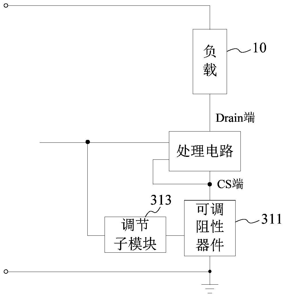
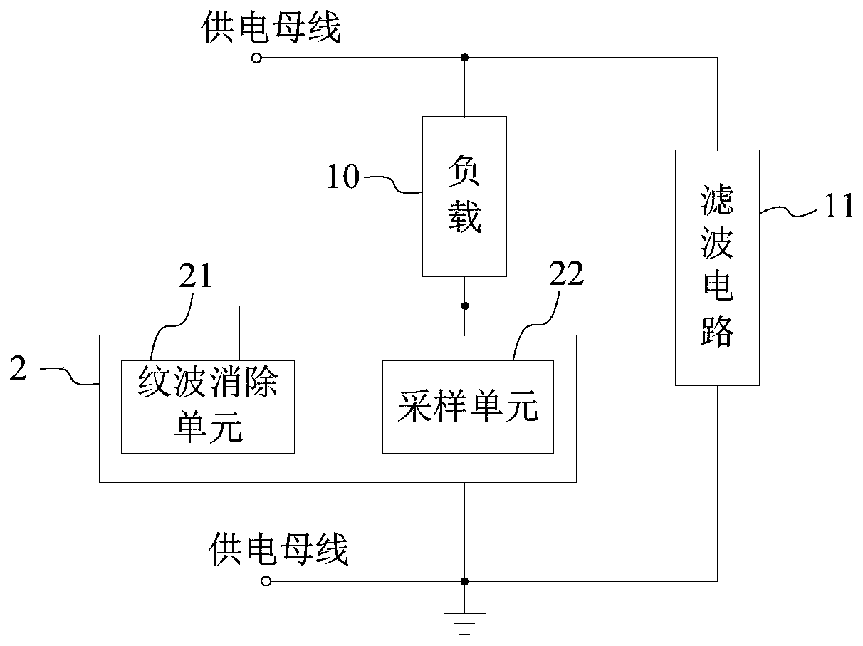
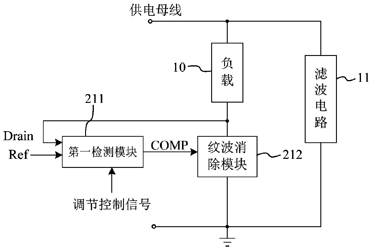
The invention discloses an adjustable resistor, an adjustment method, a current ripple elimination circuit and elimination method, a line voltage compensation circuit and compensation method, a chip and a circuit system. The adjustable resistor includes at least one impedance adjustment module which includes an adjustable resistive device and an adjustment sub-module, the adjustment sub-module cangenerate an adjustment signal based on a detection signal on a load side and sends the adjustment signal to the adjustable resistive device, and the resistance value of the adjustable resistive device on a line where the load is located is adjusted, wherein the adjusted resistance value changes inversely with a power supply signal of the load. In this way, the adjustable resistor has the technical characteristics of wide range and gentle change of the resistance value, and the control requirements of the load circuit are satisfied.

Description

technical field [0001] The present application relates to the field of circuit technology, in particular to an adjustable resistance and an adjustment method, a current ripple elimination circuit and elimination method, a line voltage compensation circuit and compensation method, a chip and a circuit system. Background technique [0002] LED (Light Emitting Diode, light-emitting diode) has many characteristics such as low working voltage, small working current, good shock resistance and shock resistance, high reliability and long life, and easy dimming. It is used in lighting, displays, indicators, etc. Widely used in many fields. However, LED devices have almost strict requirements on the driving power supply. For example, in order to ensure that the LED reflects the corresponding characteristics in the application, the LED driving power supply needs to have very high efficiency conversion, effective power, constant current accuracy, power supply life, electromagnetic compa...

Claims


Application Information

Patent Timeline
Patent Type & Authority Applications(China)
IPC IPC(8): H05B33/08G09G3/32H05B44/00
Inventor 江儒龙范敏敏郜小茹张富强祁丰
Owner SHANGHAI BRIGHT POWER SEMICONDUCTOR CO LTD
Learn More