Overturning positioning device and working method thereof

A technology of positioning device and rotating device, applied in the field of parts machining, can solve the problems of inaccurate positioning, low efficiency, inability to automate production, etc., and achieve the effect of improving work efficiency and reasonable structure design

Active Publication Date: 2019-07-02
MIBA PRECISION COMPONENTS CHINA
View PDF18 Cites 1 Cited by
  • Summary
  • Abstract
  • Description
  • Claims
  • Application Information

AI Technical Summary

Problems solved by technology

At present, the most used method is to use ordinary flipping cylinders and slides to realize flipping positioning. This method has great limitations: low efficiency (10pcs / min), inaccurate positioning (>5% positioning is not in place), parts Those whose inner hole is less than 35mm (positioning column Ø15mm) cannot be produced automatically

Method used


Image

  • Overturning positioning device and working method thereof
  • Overturning positioning device and working method thereof
  • Overturning positioning device and working method thereof

Examples


Embodiment Construction

[0033] The present invention will be further illustrated below in conjunction with the accompanying drawings and specific embodiments.

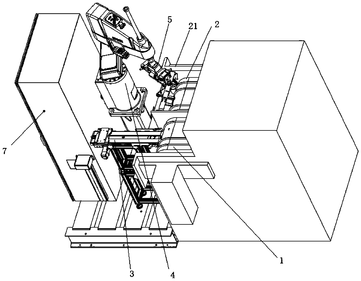
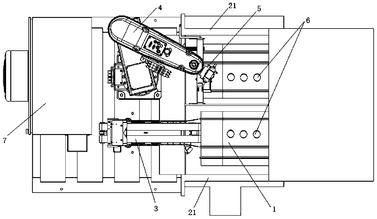
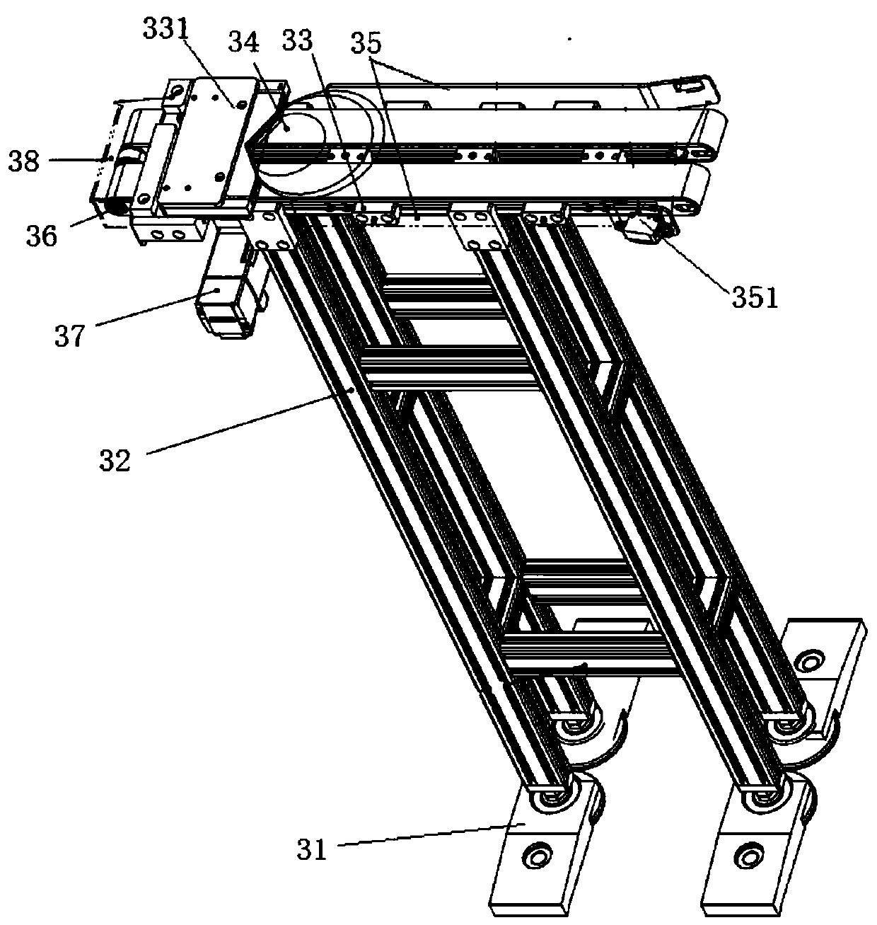
[0034] like Figure 1-5 A flipping positioning device shown includes a conveyor belt A1, a conveyor belt B2, a buffer belt mechanism 3, a manipulator 4 and a clamping and rotating mechanism 5, the conveyor belt A1 and the conveyor belt B2 are arranged in parallel, and the conveyor belt A1 and the conveyor belt B2 are fixedly set Positioning column 6 ; the buffer belt mechanism 3 is in contact with one end of the conveyor belt A1 ; the manipulator 4 is installed between the buffer belt mechanism 3 and the conveyor belt B2 ;

[0035] like Figure 3-4 As shown, in this embodiment, the clamping and rotating mechanism 5 includes a mounting and fixing portion 51, a connecting tube shell 52, a two-way cylinder 53, a connecting block 54, a rotating device 55 and a clamping jaw 56, and the connecting tube shell 52 is provided in the installation Bet...


PUM


Abstract

The invention discloses an overturning positioning device and a working method thereof. The overturning positioning device comprise a conveying belt A, a conveying belt B, a temporary storage belt mechanism, a manipulator and a clamping rotation mechanism, the conveying belt A and the conveying belt B are arranged in parallel, and positioning columns are fixedly arranged on the conveying belt A and the conveying belt B correspondingly; the temporary storage belt mechanism abuts against one end of the conveying belt A; the manipulator is mounted between the temporary storage belt mechanism andthe conveying belt B; and the clamping rotation mechanism is mounted on the manipulator. The manipulator and the clamping rotation mechanism are adopted to replace an original overturning air cylinderand an original slide way, after parts conveyed on the conveying belt A slide into the temporary storage belt structure and are taken down from the temporary storage belt by the manipulator, the partoverturning function is achieved in the process of putting the parts on the conveying belt B, double-sided surface treatment of the parts can be realized without the need of stopping operation of theconveying belt A and the conveying belt B, and the working efficiency is obviously improved.

Description

technical field [0001] The invention relates to the technical field of machining parts, in particular to a flipping positioning device and a working method thereof. Background technique [0002] For the use of the belt shot blasting machine to realize the surface treatment process of the parts, it is necessary to turn the parts from the belt A and put them on the belt B, so as to realize the surface treatment on both sides of the parts. Due to the quality requirements of the parts, the parts are placed on the belt Both A / B must be positioned in the positioning column to prevent the parts from colliding and causing defects during shot peening. At present, the most commonly used method is to use ordinary flip cylinder and slideway to achieve flip positioning. This method has great limitations: low efficiency (10pcs / min), inaccurate positioning (>5% positioning is not in place), parts The inner hole smaller than 35mm (positioning column Ø15mm) cannot be automatically produc...

Claims


Application Information

Patent Timeline
Patent Type & Authority Applications(China)
IPC IPC(8): B24C3/08
CPCB24C3/083B24C3/085
Inventor 张刚强
Owner MIBA PRECISION COMPONENTS CHINA
Why Eureka
Try Eureka