Unwinding device for raincoat production

A technology of unwinding device and raincoat, applied in the field of garment production, can solve the problems of low efficiency and labor consumption, and achieve the effects of accurate material unwinding, improving production efficiency and saving labor.

Inactive Publication Date: 2019-07-02
ANHUI YOOAN RAINGEAR
View PDF7 Cites 4 Cited by
  • Summary
  • Abstract
  • Description
  • Claims
  • Application Information

AI Technical Summary

Problems solved by technology

[0003] The purpose of the present invention is to solve the problem of labor-intensive and low efficiency in the prior art, and propose a kind of unwinding device for raincoat production

Method used


Image

  • Unwinding device for raincoat production
  • Unwinding device for raincoat production
  • Unwinding device for raincoat production

Examples


Embodiment 1

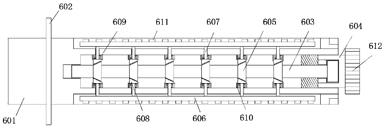
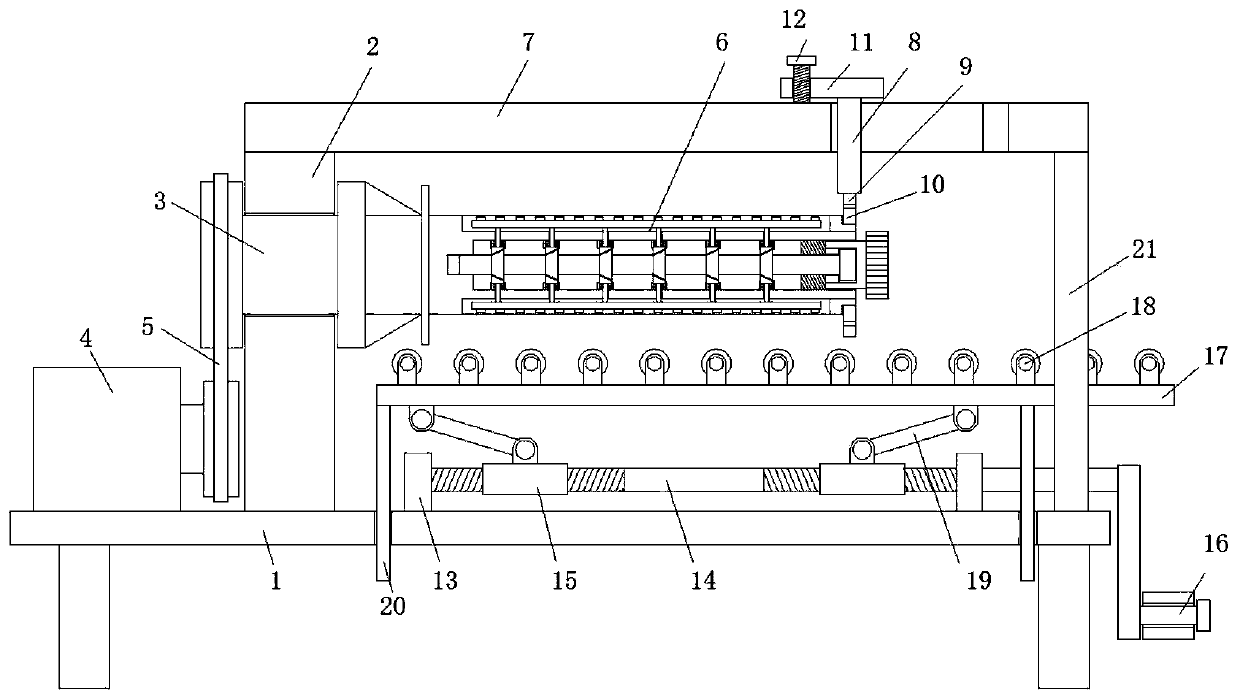
[0021] refer to Figure 1-2 , an unwinding device for raincoat production, comprising a workbench 1, a turntable 2 and a servo motor 4 are arranged on one side of the top of the workbench 1, an I-shaped turntable 3 is connected to the turntable 2 through bearing rotation, and the servomotor 4 output shaft and the I-shaped rotating disk 3 are transmission-connected with a transmission chain 5, and one side of the I-shaped rotating disk 3 is fixedly connected with a carrying shaft 6, and the carrying rotating shaft 6 includes a main shaft 601, and one end of the main shaft 601 is connected to the I-shaped rotating disk 3. One side of the rotating disk 3 is fixedly welded and the outer wall is fixedly welded to limit the side ring 2 602, and the other end of the main shaft 601 is provided with a side cavity, and an inner shaft 603 is arranged in the side cavity, and the side cavity is close to the inner wall of one side of the I-shaped rotating disk 3 A chute is provided, and one...

Embodiment 2

[0024] Such as Figure 1-2 As shown, this embodiment is basically the same as Embodiment 1. Preferably, the auxiliary charging mechanism includes a vertical plate 13. There are two vertical plates 13 and they are all fixedly connected to the top side of the workbench 1. Between the two vertical plates 13 Rotationally connected with a two-way threaded rod 14, the outer threaded sleeve of the rod body of the two-way threaded rod 14 is provided with a threaded barrel 15, one end of the two-way threaded rod 14 is connected with a rocker 16, and a bottom supporting plate 17 is arranged vertically below the bearing rotating shaft 6. The supporting plate 17 is provided with several supporting rollers 18 arranged in parallel, and a rotating supporting column 19 is rotatably connected between the bottom of the supporting plate 17 and the threaded cylinder 15 .

[0025] In this embodiment, the setting of the auxiliary loading mechanism makes it more labor-saving when people push the clo...

Embodiment 3

[0027] Such as Figure 1-2 As shown, this embodiment is basically the same as Embodiment 1. Preferably, the bottom side of the bottom supporting plate 17 is provided with a vertical sliding rod 20, and the workbench 1 is provided with a vertical through hole, and the bottom ends of the vertical sliding rods 20 are respectively slidably connected. in the vertical through hole.

[0028] In this embodiment, when the height of the bottom support plate 17 is adjusted by the crank handle 16, the stability of the bottom support plate 17 is higher.


PUM


Abstract

The invention discloses an unwinding device for raincoat production. The unwinding device for the raincoat production comprises a workbench, and a rotating seat and a servo motor are arranged on one side of the top of the workbench; a I-shaped rotating disc is rotatably connected into the rotating seat through a bearing, and a transmission chain is connected between an output shaft of the servo motor and the I-shaped rotating disc in a transmission mode; a load-bearing rotating shaft is fixedly and coaxially connected to one side of the I-shaped rotating disc, and the load-bearing rotating shaft comprises a main shaft; one end of the main shaft is fixedly welded to one side of the I-shaped rotating disc, and a second limiting side ring is fixedly welded to the outer wall of one end of themain shaft; a side cavity is formed in the other end of the main shaft, and an inner shaft is arranged in the side cavity; and a sliding groove is formed in the inner wall of the side, near the I-shaped rotating disc, of the side cavity, one end of the inner shaft is slidably connected into the sliding groove, and the other end of the inner shaft is of a T-shaped structure and a threaded sleeve ring is rotatably arranged at the other end of the inner shaft in a sleeving mode. According to the unwinding device for the raincoat production, unwinding of fabric rolls can be more accurate, the labor is saved, the production efficiency is improved, and the use requirements of people in production and living are met.

Description

technical field [0001] The invention relates to the technical field of garment production, in particular to an unwinding device for raincoat production. Background technique [0002] During the production process of the raincoat, the oily cloth used in the unwinding process, due to the large quality of the cloth roll, makes it extremely inconvenient for people to lift the cloth roll. The friction between the rotating shafts is small, so that the rotating shaft often loses rotation during the process of driving the cloth roll to unwind, which leads to the length of the unwinding being shorter than the actual need, which makes the subsequent processing inaccurate and increases the rolling capacity. The friction force inside the shaft will make people more laborious when the cloth roll is set on the outside of the shaft body, so the existing unwinding device for raincoat production cannot meet the needs of people in production and life. Contents of the invention [0003] The...

Claims


Application Information

Patent Timeline
Patent Type & Authority Applications(China)
IPC IPC(8): B65H19/12B65H75/24
CPCB65H19/123B65H75/242B65H2301/41508
Inventor 李立君金炯
Owner ANHUI YOOAN RAINGEAR
Why Eureka
Try Eureka