Prefabricated mould for pipe gallery and construction method for pipe gallery

A pipe gallery and mold technology, applied in molds, manufacturing tools, artificial islands, etc., can solve the problems of cumbersome mold assembly, inconvenient construction, trouble, etc., to improve the convenience of construction, improve the convenience of construction, and simplify the assembly process. Effect

Inactive Publication Date: 2019-07-02
厦门三航混凝土有限公司 +3
View PDF9 Cites 8 Cited by
  • Summary
  • Abstract
  • Description
  • Claims
  • Application Information

AI Technical Summary

Problems solved by technology

However, the assembly of the mold is cumbersome, and the process of putting in steel bars after splicing the pipe corridors of each section is more troublesome, which makes the construction more inconvenient

Method used


Image

  • Prefabricated mould for pipe gallery and construction method for pipe gallery
  • Prefabricated mould for pipe gallery and construction method for pipe gallery
  • Prefabricated mould for pipe gallery and construction method for pipe gallery

Examples


Embodiment 1

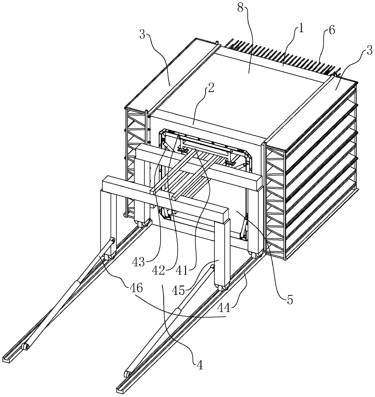
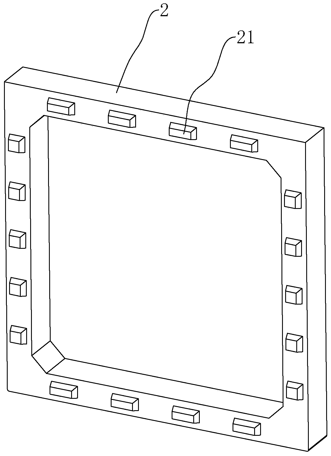
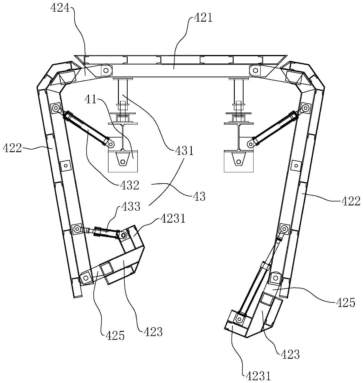
[0046] A pipe gallery prefabricated mold, such as figure 1 As shown, including fixed end mold 1, movable end mold 2, outer mold 3, inner mold 4 and bottom mold 5, movable end mold 2 and fixed end mold 1 are arranged at the two ends of outer mold 3 respectively, and movable end mold 2 It is hingedly arranged with the outer mold 3. When it is in the mold loading state, the inner mold 4 is combined with the bottom mold 5 to form a tubular inner mold 4 and is arranged in the outer mold 3, so that the inner mold 4 and the bottom mold 5 are combined. A molding space is formed between the outer molds 3 .

[0047] Such as figure 1 and figure 2 As shown, the corners at the bottom of the outer mold 3 are set as arc angles, so that the bottom of the outer mold 3 is smooth and has no edges and corners, and the handling process is not easy to be damaged, and it is more beautiful. One side of the movable end mold 2 is hinged to one side of the outer mold 3, and the other side is fastene...

Embodiment 2

[0054] A method of pipe gallery construction, such as Figure 1 to Figure 4 As shown, the construction of the pipe gallery prefabricated mold in the first embodiment includes the following steps:

[0055] S1. Prepare the prefabricated mold of the pipe gallery and clean it;

[0056] S2. Insert steel bars 6 into each reinforcement hole 11 of the fixed end mold 1, and reserve a section outside the fixed end mold 1;

[0057] S3, set the rubber plug 13 on the steel bar 6, and insert it into the steel bar hole 11, and then bind the steel bar skeleton for forming the pipe gallery 8 on the steel bar 6 located inside the fixed end mold 1;

[0058] S4. Insert the water-stop steel plate 7 into the reserved notch 12 of the fixed end mold 1, and insert a hollow rubber strip 14 into the reserved notch 12 to fix the water-stop steel plate 7;

[0059] S5, fixing the fixed end mold 1 with the reinforcement skeleton and the outer mold 3, and opening the movable end mold 2 to wait for the inst...


PUM


Abstract

The invention discloses a prefabrication mould for a pipe gallery, and relates to the technical field of engineering moulds. According to the key points of the technical scheme, the prefabrication mould comprises a fixed end mould body, a movable end mould body, an outer side mould body, an inner mould body and a bottom mould body, wherein the movable end mould body and the fixed end mould body are arranged at the two ends of the outer side mould body correspondingly, the movable end mould body is hinged to the outer side mould body, the inner mould body and the bottom mould body are combinedand arranged in the outer side mould body, and a forming space is formed between the inner mould body and the bottom mould body after the inner mould body and the bottom mould body are combined with the outer side mould body. The two ends of the inner mold body abut against the fixed end mold body and the movable end mold body, reinforcing steel bars are embedded in the forming space, the reinforcing steel bars penetrate through the fixed end mold body, the fixed end mold body is installed at the end of the outer mold body, a plurality of reinforcing steel bar hole positions for the reinforcing steel bars extending out are formed in the fixed end mold body, and the reinforcing steel bar hole positions correspond to the reinforcing steel bars. By extending the embedded steel bars out of thesteel bar hole positions, the steel bars are exposed after the pipe gallery is formed, construction of each section of the pipe gallery during splicing is convenient, the mould assembly is convenient, and the advantage of improving the construction convenience is achieved.

Description

technical field [0001] The invention relates to the technical field of engineering moulds, more specifically, it relates to a pipe gallery prefabricated mold and a pipe gallery construction method. Background technique [0002] Pipe gallery, that is, the corridor of pipelines. Many pipelines in chemical and related factories are gathered together and arranged along the device or outside the factory building, usually in the air, supported by brackets, forming a similar appearance to corridors. There are also a few pipe galleries located underground. In the prior art, the prefabricated pipe gallery replaces the traditional cast-in-place pipe gallery. It is the trend of building industrialization. The outer mold and the inner mold must be used in the production of the prefabricated pipe gallery. The pouring space is formed by the cooperation of the outer mold and the inner mold. The pipe gallery can be formed by pouring. After the pipe gallery is formed, the pipe gallery of e...

Claims


Application Information

Patent Timeline
Patent Type & Authority Applications(China)
IPC IPC(8): E02D29/045B28B7/22B28B23/02
CPCB28B7/22B28B23/022E02D29/10
Inventor 蔡清程唐建明刘晓燕贾良飞唐智峰
Owner 厦门三航混凝土有限公司
Why Eureka
Try Eureka