Supercharge Your Innovation With Domain-Expert AI Agents!

Efficient energy-saving automobile thermolator and automobile engine assembly

A high-efficiency, energy-saving, thermostat technology, applied in the direction of machine/engine, engine components, engine cooling, etc., can solve the problems of prolonged engine warm-up time, low engine temperature, engine damage, etc., and achieve the effect of automatically changing the cycle range

Active Publication Date: 2019-07-02
北京长城华冠汽车技术开发有限公司
View PDF6 Cites 1 Cited by
  • Summary
  • Abstract
  • Description
  • Claims
  • Application Information

AI Technical Summary

Problems solved by technology

When the temperature of the cooling water is sufficient to cool down the engine, the main valve head of the thermostat and the water inlet of the radiator pipe correspond to stoppers, and the circulating water flowing out of the cylinder head outlet pipe of the engine enters the water inlet of the water pump pipe, and is pumped by the water pump. Circulation is pumped into the engine to cool down the engine; when the temperature of the cooling water is high, the bypass valve head of the thermostat and the water inlet of the water pump pipe correspond to stoppers, and the circulating water flowing out of the cylinder head outlet pipe of the engine enters the radiator The water inlet of the pipeline enters the engine after being cooled by the radiator to cool down the engine; if the main valve head of the thermostat is opened too late, it will cause the engine to overheat; if the main valve head is opened too early, the engine warm-up time will be prolonged. make the engine temperature too low
Traditional thermostats are mainly wax-type thermostats. The opening of the main valve head is adjusted by changing the shape of the paraffin. There will be a certain delay in the melting of the paraffin. Long-term use will cause engine damage and waste energy.

Method used


Image

  • Efficient energy-saving automobile thermolator and automobile engine assembly
  • Efficient energy-saving automobile thermolator and automobile engine assembly
  • Efficient energy-saving automobile thermolator and automobile engine assembly

Examples


Embodiment Construction

[0022] The technical solutions of the present invention will be clearly and completely described below in conjunction with the accompanying drawings. Apparently, the described embodiments are some of the embodiments of the present invention, but not all of them. Based on the embodiments of the present invention, all other embodiments obtained by persons of ordinary skill in the art without making creative efforts belong to the protection scope of the present invention.

[0023] In the description of the present invention, it should be noted that the terms "center", "upper", "lower", "left", "right", "vertical", "horizontal", "inner", "outer" etc. The indicated orientation or positional relationship is based on the orientation or positional relationship shown in the drawings, and is only for the convenience of describing the present invention and simplifying the description, rather than indicating or implying that the referred device or element must have a specific orientation, ...


PUM


Abstract

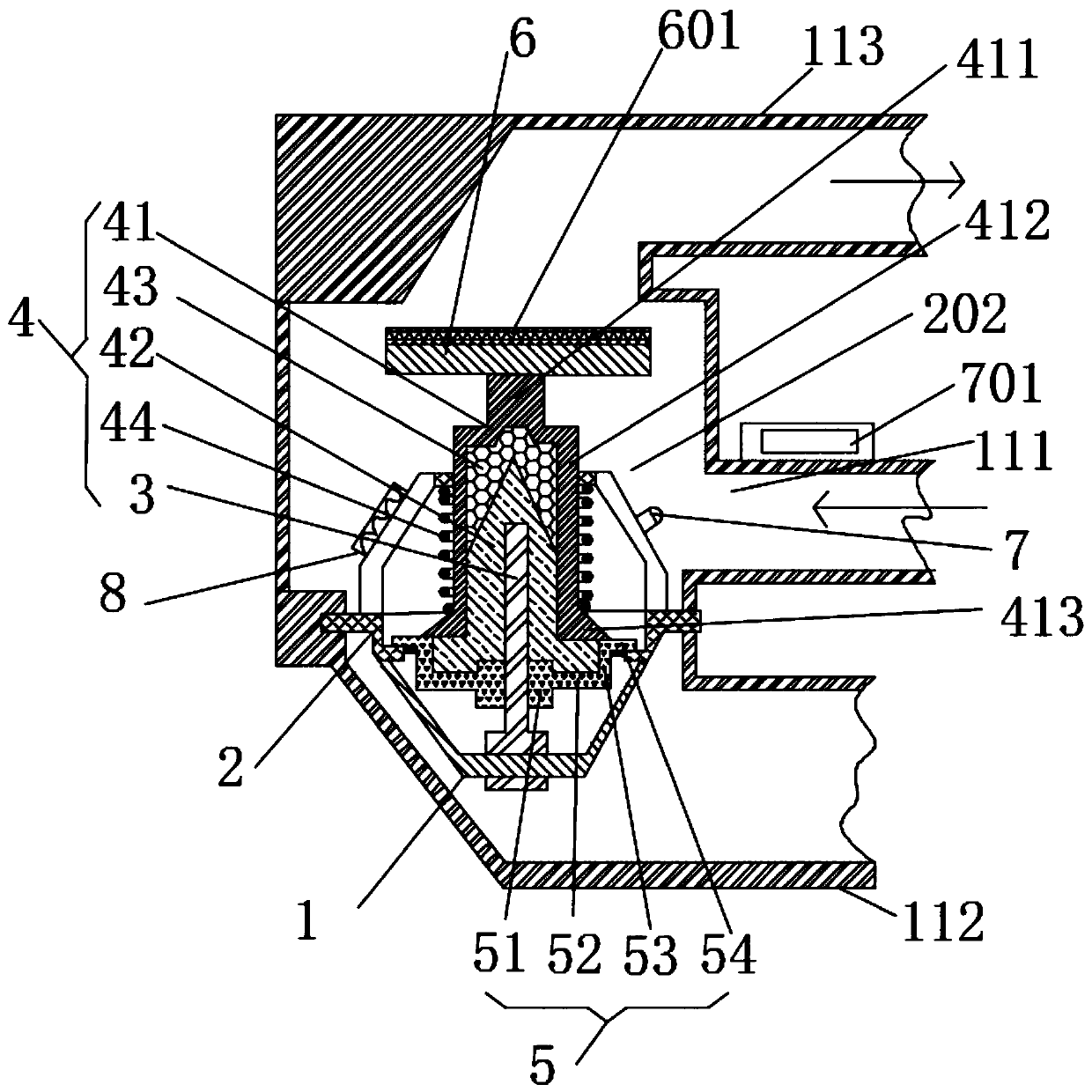
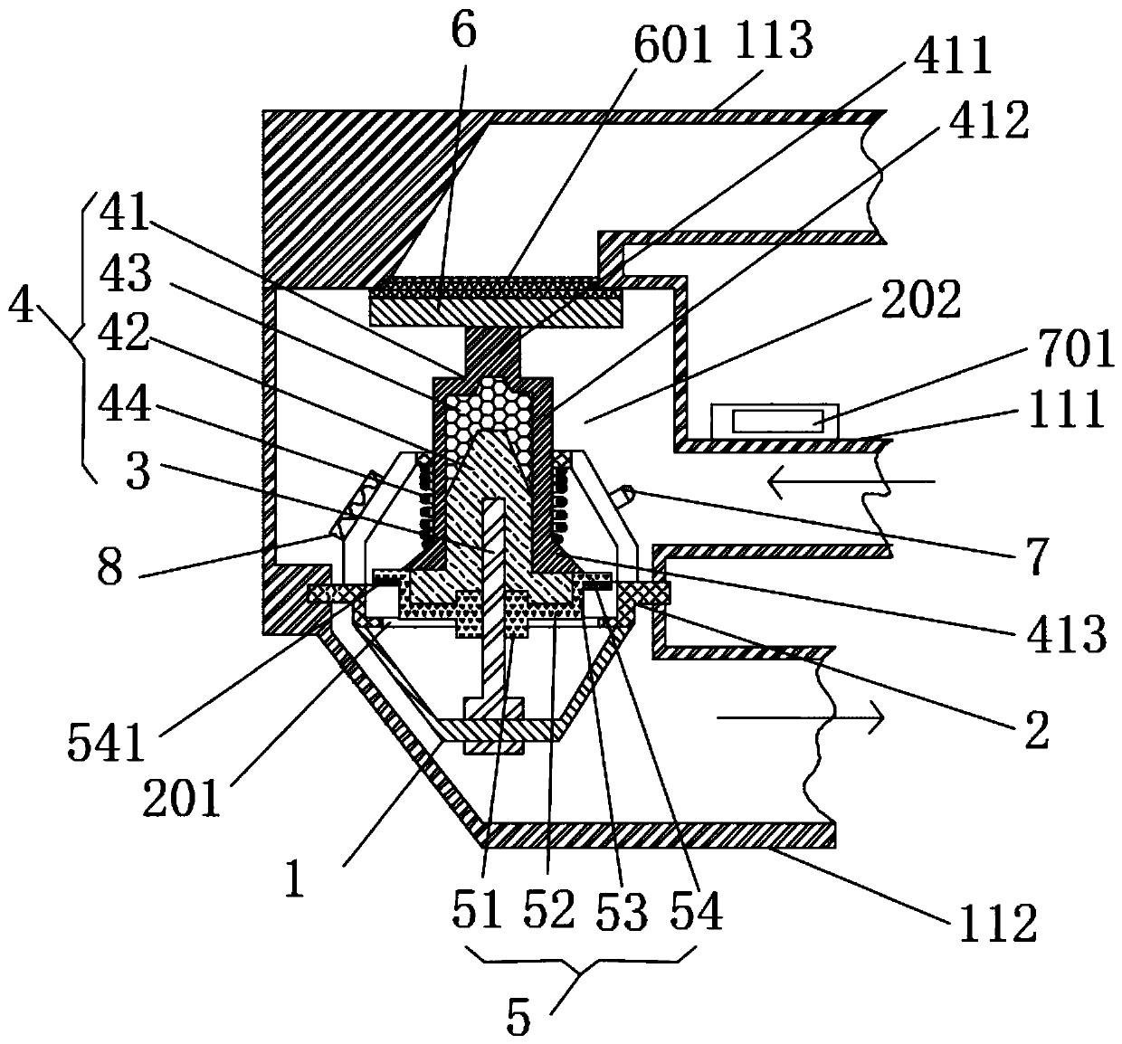
The invention relates to the automobile technical field, in particular to an efficient energy-saving automobile thermolator and an automobile engine assembly. The efficient energy-saving automobile thermolator comprises a controller, a temperature sensor, a heater and a three-way valve mounted on a circulating pipeline in a gas cylinder cover, wherein a bypass valve head which correspondingly stops a water inlet of a water pump tube and a main valve head which correspondingly stops a water inlet of a radiator tube are arranged on the three-way valve; a water-passing gap is formed between the bypass valve head and the main valve head; the water-passing gap communicates with a water outlet tube of a gas cylinder cover; a thermal expansion jacking piston is controlled to move through the temperature sensor, the controller and the heater, so that timely switching of a circulating pipeline is realized, an engine is cooled, a circulating range of cooling liquid is automatically changed, andthe problem that engine damages and energy waste are caused as the valve of the automobile thermolator is prevented from being opened too early to cause a too low engine temperature or a paraffin valve is prevented from being opened in a delayed mode to cause too late cooling is solved.

Description

technical field [0001] The invention relates to the technical field of automobiles, in particular to a high-efficiency and energy-saving automobile thermostat and an automobile engine assembly. Background technique [0002] The car thermostat automatically adjusts the amount of water entering the radiator according to the temperature of the cooling water, and changes the water circulation range to adjust the heat dissipation capacity of the cooling system to ensure that the engine works within a suitable temperature range. The thermostat must be kept in good technical condition, otherwise it will seriously affect the normal operation of the engine. When the temperature of the cooling water is sufficient to cool down the engine, the main valve head of the thermostat and the water inlet of the radiator pipe correspond to stoppers, and the circulating water flowing out of the cylinder head outlet pipe of the engine enters the water inlet of the water pump pipe, and is pumped by...

Claims


Application Information

Patent Timeline
IPC IPC(8): F01P7/16F01P11/16
CPCF01P7/165F01P11/16F01P2007/146F01P2050/22
Inventor 代宏伟刘毅
Owner 北京长城华冠汽车技术开发有限公司
Features
  • R&D
  • Intellectual Property
  • Life Sciences
  • Materials
  • Tech Scout
  • Unparalleled Data Quality
  • Higher Quality Content
  • 60% Fewer Hallucinations
Learn More