Eureka AIR delivers breakthrough ideas for toughest innovation challenges, trusted by R&D personnel around the world.

Fixing unit and base fixing element

A technology of fixing components and fixing units, which is applied in the direction of connecting components, digital data processing parts, instruments, etc., can solve the problems of wasting man-hours, complicated manufacturing processes, inability to rework, wire drawing, etc., and achieve the effect of easy assembly and disassembly

Pending Publication Date: 2019-07-02
ASIA VITAL COMPONENTS SHENZHEN CO LTD
View PDF10 Cites 0 Cited by
  • Summary
  • Abstract
  • Description
  • Claims
  • Application Information

AI Technical Summary

Problems solved by technology

[0004] However, since the extension boss has to wait for the time of high-temperature melting and cooling and shaping, and after being melted by high temperature, it will cause waste of man-hours such as wire drawing and complicated manufacturing process, and it cannot be reworked, so the existing disadvantages are the present case. target to improve

Method used


Image

  • Fixing unit and base fixing element
  • Fixing unit and base fixing element
  • Fixing unit and base fixing element

Examples


Embodiment Construction

[0040] The above-mentioned purpose of the present invention and its structural and functional characteristics will be described according to the preferred embodiments of the accompanying drawings.

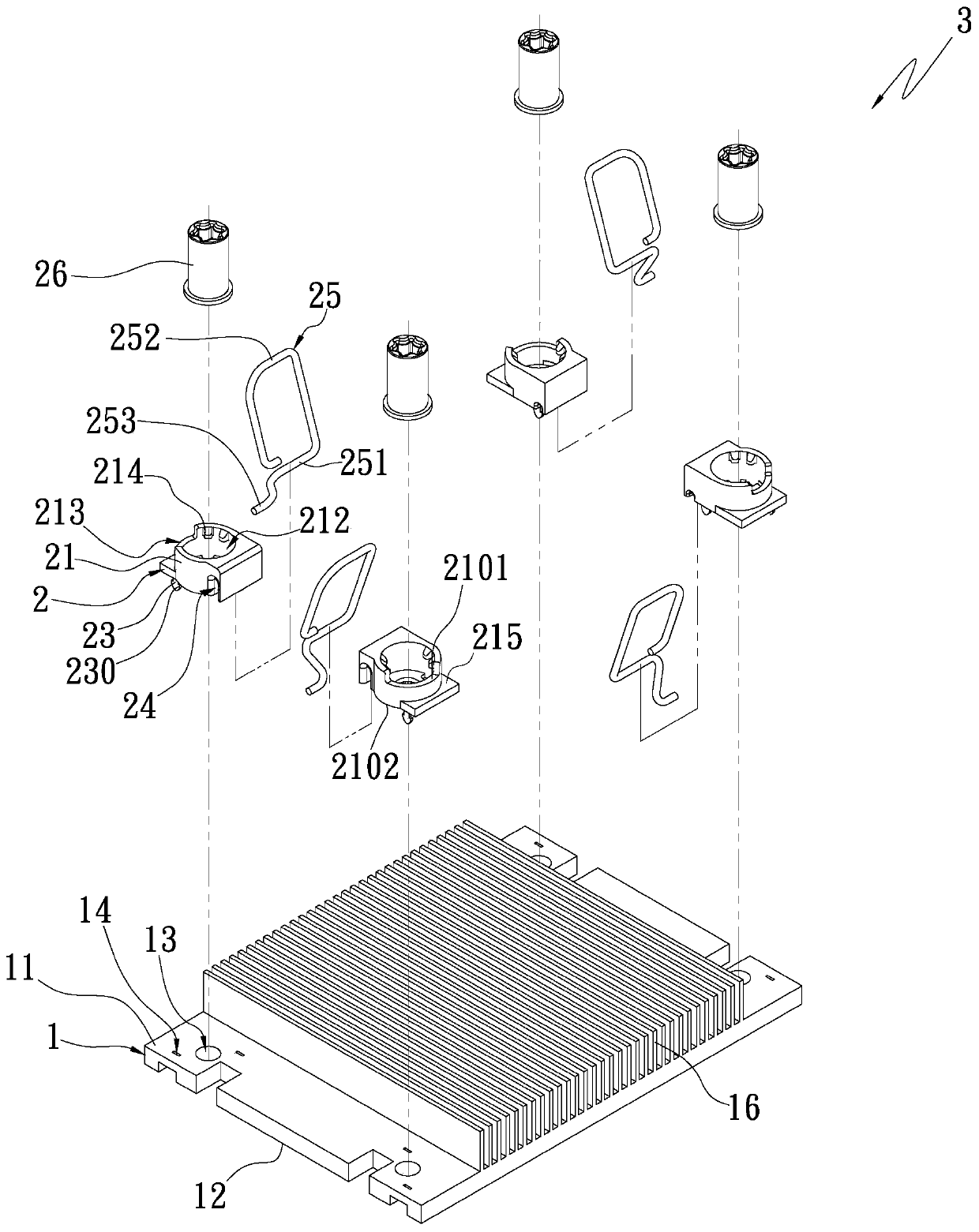
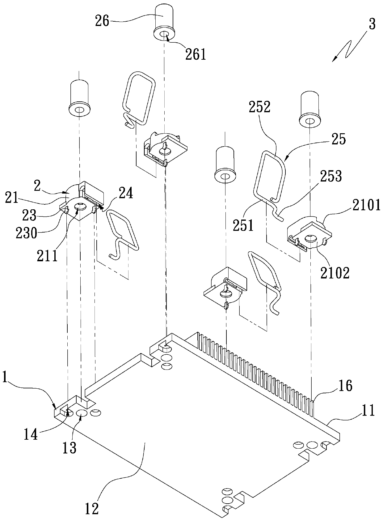
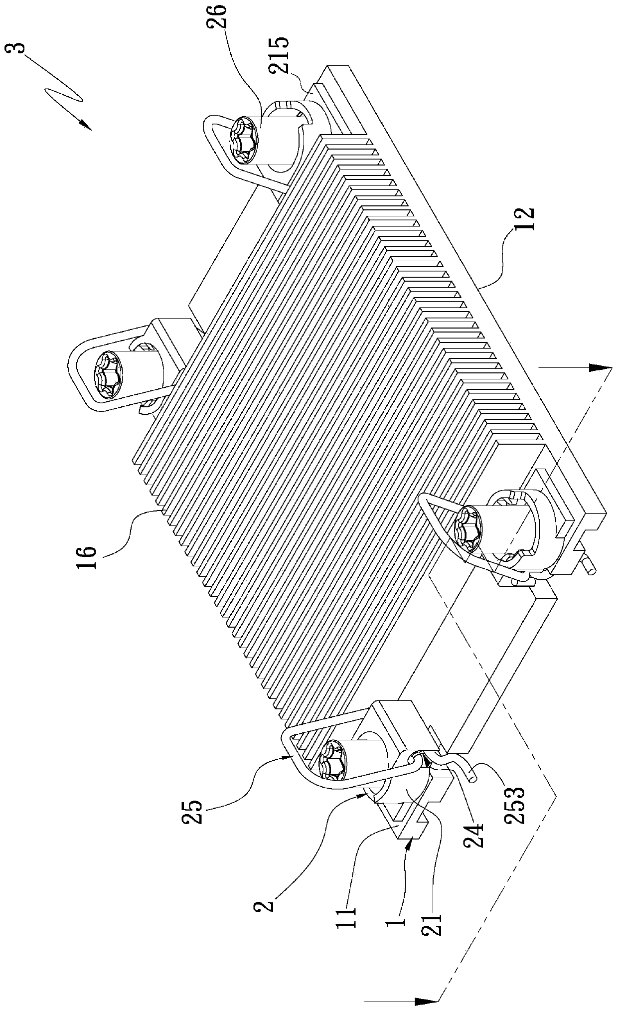
[0041] The present invention is a fixing unit and a base fixing element, please refer to Figure 1A It is a three-dimensional exploded schematic view of the first embodiment of the present invention; Figure 1B It is a perspective exploded schematic diagram of another viewing angle of the first embodiment of the present invention; figure 2 It is a three-dimensional combination schematic diagram of the first embodiment of the present invention; Figure 2A It is a partial cross-sectional schematic diagram of the first embodiment of the present invention; Figure 2B It is a partial cross-sectional schematic diagram of an embodiment of the first embodiment of the present invention. The base fixing element is applied to a solid or cavity metal (gold, silver, copper, aluminum, stainle...


PUM


Abstract

The invention provides a fixing unit and a base fixing element. The base fixing element comprises a base and a plurality of fixing units. wherein the base is provided with a top side, a bottom side, aplurality of holes and a plurality of fixing holes; the plurality of holes and the plurality of fixing holes respectively penetrate through the top side and the bottom side of the base; the pluralityof fixing holes are positioned outside the periphery of the corresponding hole; the fixing unit is provided with a seat part and a plurality of combining parts which are arranged on the top side corresponding to the base; the base portion is provided with an open hole communicated with the corresponding hole, the combination portions are arranged on the lower side of the base portion, one end ofeach combination portion is provided with one or more blocking end portions, and the blocking end portions of the combination portions penetrate through and correspond to the fixing holes so that theblocking end portions can abut against the bottom side of the base.

Description

technical field [0001] The invention relates to a fixing unit and a base fixing element, in particular to a base fixing element which is easy to assemble, disassemble and operate. Background technique [0002] Electronic equipment is equipped with a variety of different types of electronic components, and various electronic components are responsible for providing electronic equipment for different tasks. Among them, the central processing unit or other chips that are responsible for providing calculations will generate high temperatures during operation, so It is necessary to dissipate heat through cooling elements to prevent the central processing unit or other chips from being burned. [0003] Common heat dissipation elements include radiators, vapor chambers, heat dissipation fin groups, etc., and the heat dissipation elements must be in contact with the chip or the central processing unit or heat source through close contact, so that there is no thermal resistance betwe...

Claims


Application Information

Patent Timeline
IPC IPC(8): G06F1/18G06F1/20F16B13/10
CPCG06F1/183G06F1/20F16B13/04F16B13/10
Inventor 林胜煌
Owner ASIA VITAL COMPONENTS SHENZHEN CO LTD
Why Eureka
Eureka Blog
Learn More