Rotor iron core and permanent magnet synchronous motor

A rotor core and permanent magnet synchronization technology, applied in the direction of electric components, magnetic circuit rotating parts, magnetic circuits, etc., can solve the problems of electrical system imbalance, motor power imbalance, damage to motor components, etc., to achieve convenient assembly, Conducive to precise fixation and the effect of preventing positional deviation

Pending Publication Date: 2019-07-02
安徽明腾永磁机电设备有限公司 +1
View PDF0 Cites 4 Cited by
  • Summary
  • Abstract
  • Description
  • Claims
  • Application Information

AI Technical Summary

Problems solved by technology

[0010] 1. Destroy the stability of the motor operation;
[0011] 2. Cause the electrical system to be unbalanced;
[0013] 4. Demagnetize the permanent magnet;
[0014] 5. Unbalance the power of the motor and damage the motor components

Method used


Image

  • Rotor iron core and permanent magnet synchronous motor
  • Rotor iron core and permanent magnet synchronous motor
  • Rotor iron core and permanent magnet synchronous motor

Examples


Embodiment Construction

[0042] Embodiments of the present invention will be described in detail below in conjunction with the accompanying drawings.

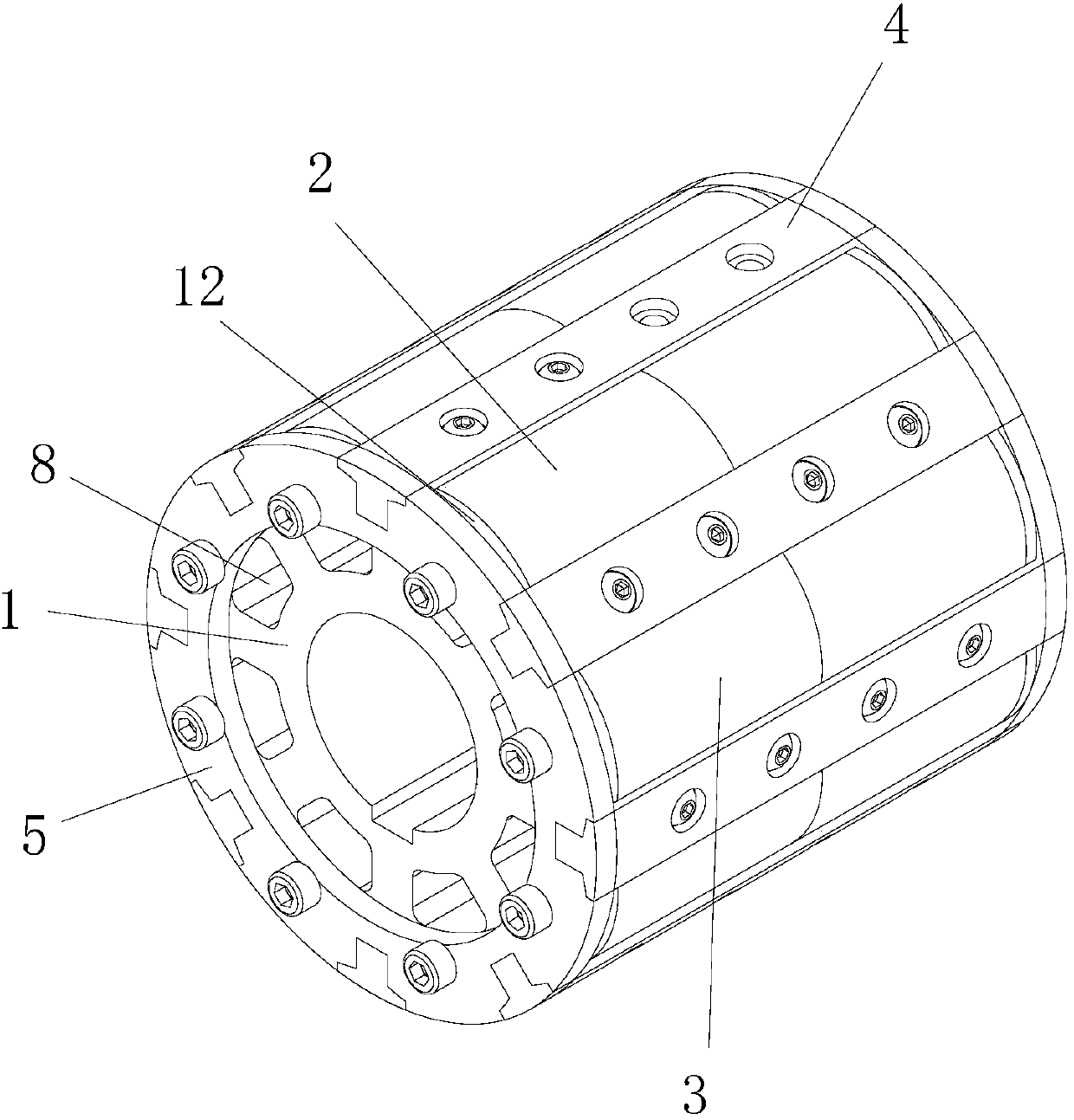
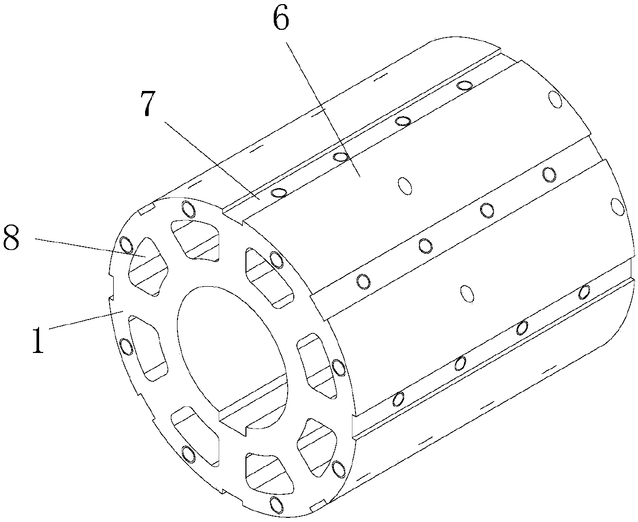
[0043] Such as Figure 1 to Figure 5 As shown, an embodiment of the present invention provides a rotor core used in a permanent magnet synchronous motor, the rotor core includes:

[0044] Rotor bracket 1, which is cylindrical, with a shaft hole in the middle for passing the rotating shaft;

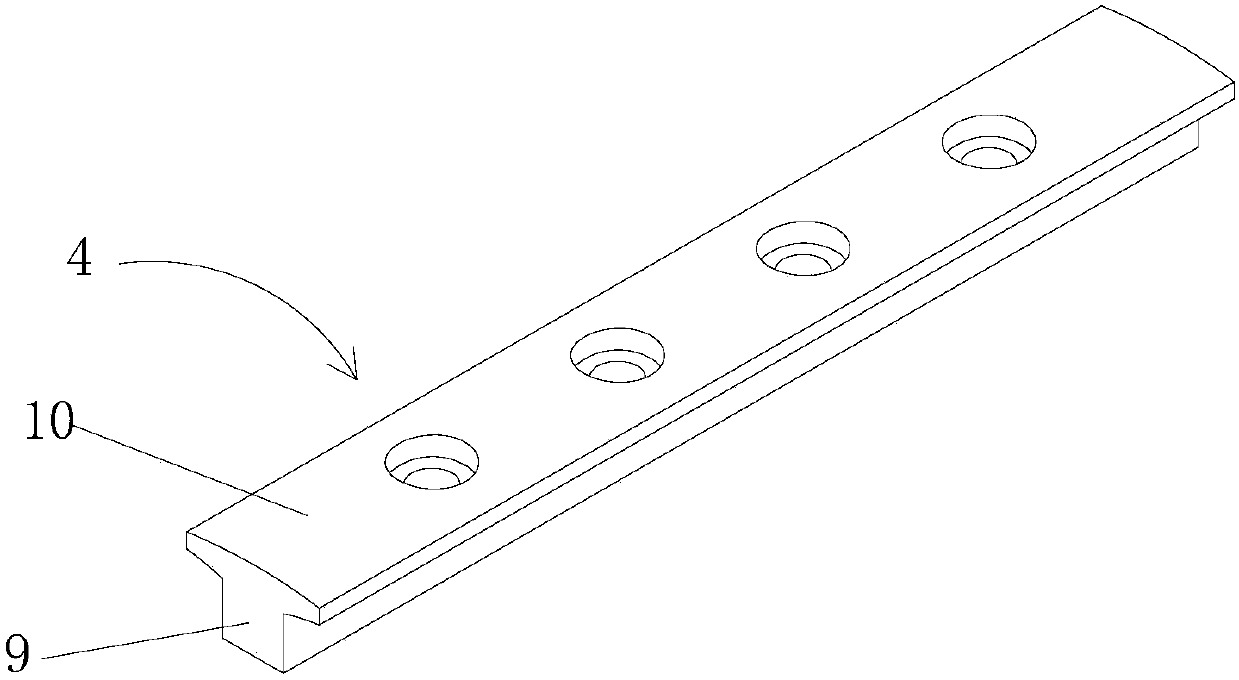
[0045] Damping pressure block 4, which is strip-shaped and has a plurality of damping pressure blocks 4 respectively installed on the outer surface of the rotor support 1 along the axial direction of the rotor support;

[0046] There are multiple permanent magnets, and the multiple permanent magnets are divided into multiple groups. A group of permanent magnets are surface-mounted on the outer surface of the rotor support 1 between two adjacent damping pressure blocks 4, such as permanent The magnets are fixed on the outer surface of the rotor bracket 1, so that ...


PUM


Abstract

The invention provides a rotor iron core and a permanent magnet synchronous motor. The rotor iron core comprises a rotor support which is cylindrical; multiple damping pressing blocks which are strip-shaped and arranged on the outer surface of the rotor support along the axial direction of the rotor support; multiple sets of permanent magnets of which each set of permanent magnets are surface-mounted on the rotor support between the two adjacent damping pressing blocks along the axial direction of the rotor support and abut against the damping pressing blocks so that the damping pressing blocks are enabled to press and fix the permanent magnets; and two damping end rings which are arranged at both ends of the rotor support, wherein the two ends of the damping pressing blocks are respectively connected with the two damping end rings to cooperate and form damping windings, and the damping windings can cut the magnetic force lines generated by the stator windings in the permanent magnet synchronous motor when the permanent magnet synchronous motor oscillates. The rotor iron core can stabilize the relative position between the permanent magnets and the rotor support and can effectivelyreduce the oscillation phenomenon in the permanent magnet synchronous motor.

Description

technical field [0001] The invention relates to the technical field of motors, in particular to a rotor iron core and a permanent magnet synchronous motor. Background technique [0002] Among the structural forms of small and medium-sized permanent magnet synchronous motors, surface-mounted permanent magnet synchronous motors have been widely used in permanent magnet synchronous motors due to their simple structure and low manufacturing cost. At the same time, the pole structure of the permanent magnet with raised surface is also easy to achieve optimal design, making the air-gap magnetic field flux density waveform of the motor more likely to approach a sine wave, which can improve the performance of the motor and the entire electric transmission system. [0003] Among the structural forms of the existing small and medium-sized permanent magnet synchronous motors, the common fixing methods of the permanent magnets of the surface-mounted permanent magnet synchronous motors a...

Claims


Application Information

Patent Timeline
Patent Type & Authority Applications(China)
IPC IPC(8): H02K1/27H02K1/32
CPCH02K1/278H02K1/32H02K2201/15
Inventor 梅洛明孙建锐贾小燕于万娟
Owner 安徽明腾永磁机电设备有限公司
Why Eureka
Try Eureka