
Heat dissipation device for electrical equipment

A technology for heat dissipation devices and electrical equipment, which is applied in the construction parts of electrical equipment, electrical components, cooling/ventilation/heating transformation, etc., which can solve the problems of low heat dissipation efficiency and achieve the effect of simple structure and increased heat dissipation efficiency

Inactive Publication Date: 2019-07-02
徐州益利亚重工科技有限公司
View PDF0 Cites 3 Cited by
  • Summary
  • Abstract
  • Description
  • Claims
  • Application Information

AI Technical Summary

Problems solved by technology

However, the heat dissipation efficiency of existing electrical equipment is not high. Therefore, a heat dissipation device for electrical equipment is proposed

Method used


Image

  • Heat dissipation device for electrical equipment
  • Heat dissipation device for electrical equipment
  • Heat dissipation device for electrical equipment

Examples


Embodiment Construction

[0013] The following will clearly and completely describe the technical solutions in the embodiments of the present invention with reference to the accompanying drawings in the embodiments of the present invention. Obviously, the described embodiments are only some, not all, embodiments of the present invention.

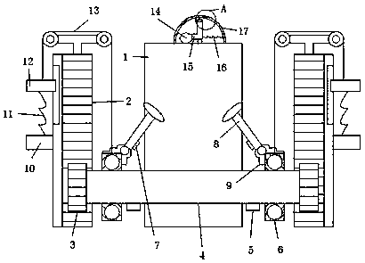
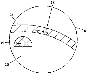
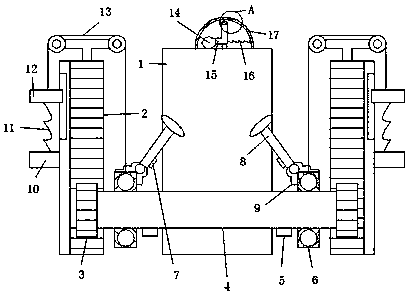
[0014] refer to Figure 1-2 , a cooling device for electrical equipment, comprising a power equipment box 1, support blocks are placed on both sides of the power equipment box 1, a rack 2 is connected to the front side wall of the support block, and a gear 3 is meshed with the rack 2, and the two gears 3 The opposite side walls are connected by the cooling water pipe 4, the cooling water pipe 4 is located on the front side of the power equipment box 1, the top of the power equipment box 1 is connected to the two ends of the arc cover 17, and the inner side wall of the arc cover 17 is connected to the first One end of the conductive sheet 18 and the third spring 16, t...


PUM


Abstract

The invention discloses a heat dissipation device for electrical equipment, including a power equipment box. Support blocks are placed on the two sides of the power equipment box respectively. The front side wall of each support block is connected with a rack. Each rack is meshed with a gear. The opposite side walls of the two gears are connected by a cooling water pipe. The heat dissipation device has a simple structure. Through a combined structure of the cooling water pipe and swing rods, when the power equipment box emits heat, an airbag expands to cause an L-shaped rod to deflect, a second conductive sheet contacts a first conductive sheet, electromagnets attract iron blocks downward, the gears roll upward along the racks through pull ropes, the cooling water pipe rolls upward along the power equipment box to absorb heat, and thus, primary heat dissipation of the power equipment box is completed. When the cooling water pipe rotates, a first magnet attracts a second magnet intermittently. Under the action of first springs, the swing rods swing, and fan blades swing for air cooling, which enhances the heat dissipation efficiency.

Description

technical field [0001] The invention relates to the technical field of electrical equipment, in particular to a cooling device for electrical equipment. Background technique [0002] For electrical equipment, there are generally heating components of key equipment. It is necessary to dissipate the heat inside the electrical equipment as soon as possible to ensure the stable and reliable operation of the equipment. However, the heat dissipation efficiency of the existing electrical equipment is not high. Therefore, a heat dissipation device for the electrical equipment is proposed. Contents of the invention [0003] The purpose of the present invention is to solve the shortcomings in the prior art, and propose a cooling device for electrical equipment. [0004] In order to achieve the above object, the present invention adopts the following technical solutions: a cooling device for electrical equipment, including a power equipment box, support blocks are placed on both sid...

Claims


Application Information

Patent Timeline
Patent Type & Authority Applications(China)
IPC IPC(8): H05K7/20
CPCH05K7/20209H05K7/20218
Inventor 刘贵来
Owner 徐州益利亚重工科技有限公司
Learn More