Disc rotary type multi-channel electron beam rapid forming method
A multi-channel, electron beam technology, applied in the field of additive manufacturing, can solve problems such as powerlessness, and achieve the effect of reducing deflection angle, improving forming accuracy and forming quality, and ensuring beam quality
- Summary
- Abstract
- Description
- Claims
- Application Information
AI Technical Summary
Problems solved by technology
Method used
Image
Examples
Embodiment 1
[0039] The manufacturing method of the present embodiment comprises the following steps:
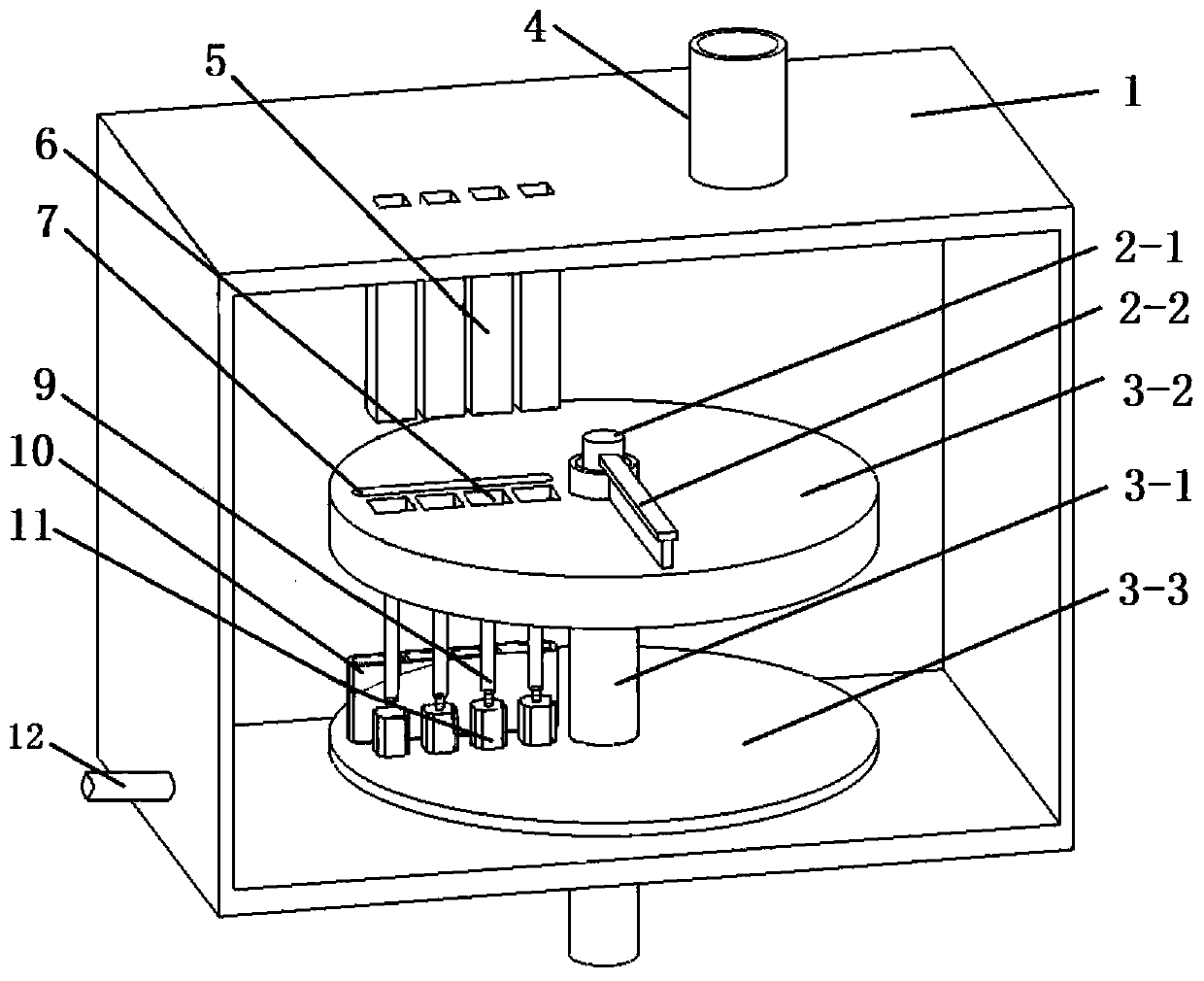
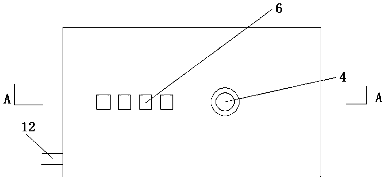
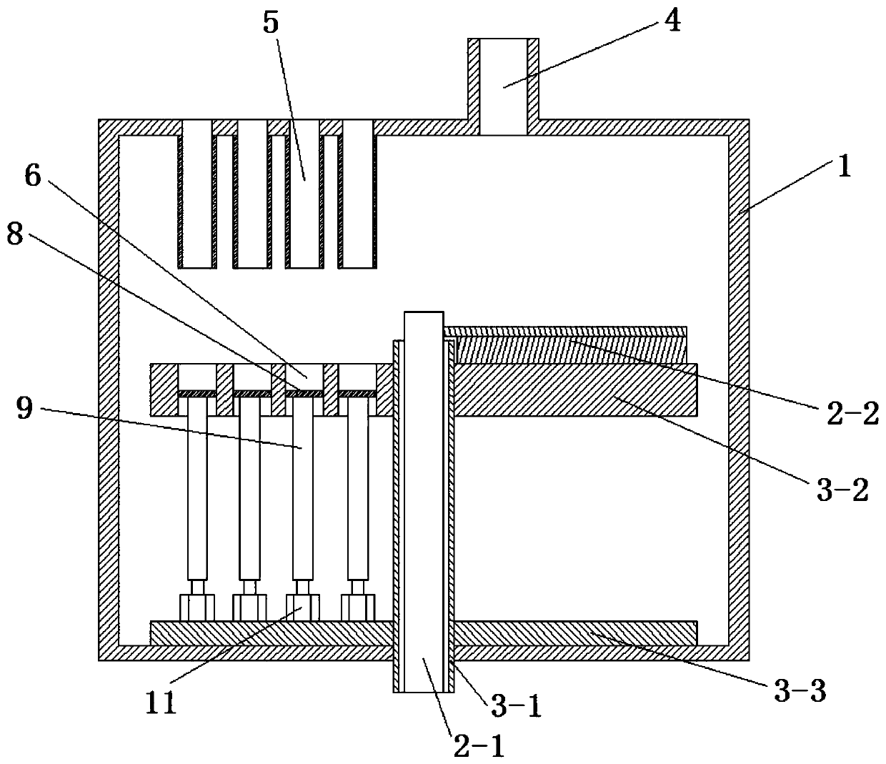
[0040] Step 1. On the 4 forming areas 6 of the disc table 3-2 of the disc rotary multi-channel electron beam rapid prototyping equipment, respectively place 4 titanium part models correspondingly, each with a size of 10mm × 10mm × 10mm (length × width × height), and then use the layered software Build Assembler to slice the four titanium part models and import the obtained slice data into the computer 13 of the control system of the disc-rotating multi-channel electron beam rapid prototyping equipment; The four forming areas 6 are arranged at equal intervals of 50mm along the radial direction of the disc table 3-2; the slice thicknesses of the four titanium part models obtained by slicing are all 200 μm;
[0041] Step 2: Establish a polar coordinate system on the surface of the disk workbench 3-2 through the computer 13, take the center of the disk workbench 3-2 as the polar coordinate o...
Embodiment 2
[0048] The manufacturing method of the present embodiment comprises the following steps:
[0049] Step 1. Place one Ti part model, one Cu part model, and one Ni part on the four forming areas 6 of the disc table 3-2 of the disc rotary multi-channel electron beam rapid prototyping equipment. model, one Sn part model, the size is 10mm×10mm×10mm (length×width×height), and then use the layering software Build Assembler to slice the above four part models and import the sliced data into the disc In the computer 13 in the control system of the rotary multi-channel electron beam rapid prototyping equipment; the 4 forming areas 6 are arranged at equal intervals of 50mm along the radial direction of the disc table 3-2; the 4 part models are sliced The slice thickness obtained by processing corresponds to 30 μm, 70 μm, 150 μm and 200 μm respectively;
[0050] Step 2: Establish a polar coordinate system on the surface of the disk workbench 3-2 through the computer 13, take the center ...
Embodiment 3
[0057] The manufacturing method of the present embodiment comprises the following steps:
[0058] Step 1. Place one Ti part model, one Cu part model, and one Fe part on the four forming areas 6 of the disc table 3-2 of the disc rotary multi-channel electron beam rapid prototyping equipment. model and one Sn part model, the size of which is 10mm×10mm×10mm (length×width×height), and then use the layering software Build Assembler to slice the above four part models and import the sliced data into the disc In the computer 13 in the control system of the rotary multi-channel electron beam rapid prototyping equipment; the 4 forming areas 6 are arranged at equal intervals of 50mm along the radial direction of the disc table 3-2; the 4 part models are sliced The slice thickness obtained by processing corresponds to 30 μm, 70 μm, 180 μm and 200 μm respectively;
[0059] Step 2: Establish a polar coordinate system on the surface of the disk workbench 3-2 through the computer 13, take...
PUM
| Property | Measurement | Unit |
|---|---|---|
| Thickness | aaaaa | aaaaa |
Abstract
Description
Claims
Application Information
 - R&D
- Intellectual Property
- Life Sciences
- Materials
- Tech Scout
- Unparalleled Data Quality
- Higher Quality Content
- 60% Fewer Hallucinations
Browse by: Latest US Patents, China's latest patents, Technical Efficacy Thesaurus, Application Domain, Technology Topic, Popular Technical Reports.
© 2025 PatSnap. All rights reserved.Legal|Privacy policy|Modern Slavery Act Transparency Statement|Sitemap|About US| Contact US: help@patsnap.com


