A Disc Rotating Multi-channel Electron Beam Rapid Prototyping Method

A multi-channel, electron beam technology, applied in the field of additive manufacturing, can solve problems such as powerlessness, achieve the effect of reducing deflection angle, improving forming accuracy and forming quality, and realizing rapid prototyping

Active Publication Date: 2020-04-17
NORTHWEST INSTITUTE FOR NON-FERROUS METAL RESEARCH
View PDF10 Cites 0 Cited by
  • Summary
  • Abstract
  • Description
  • Claims
  • Application Information

AI Technical Summary

Problems solved by technology

[0004] The current electron beam rapid prototyping technology can only realize the preparation of a single metal material sample or part at the same time, but it is helpless for the simultaneous sintering preparation of multiple metal material samples or parts

Method used


Image

  • A Disc Rotating Multi-channel Electron Beam Rapid Prototyping Method
  • A Disc Rotating Multi-channel Electron Beam Rapid Prototyping Method
  • A Disc Rotating Multi-channel Electron Beam Rapid Prototyping Method

Examples


Embodiment 1

[0039] The manufacturing method of the present embodiment comprises the following steps:

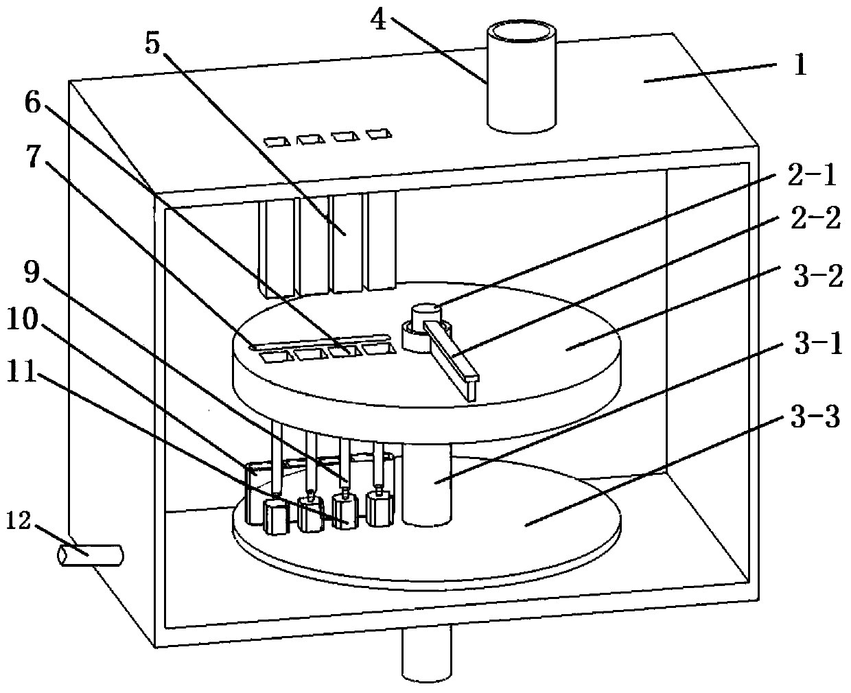
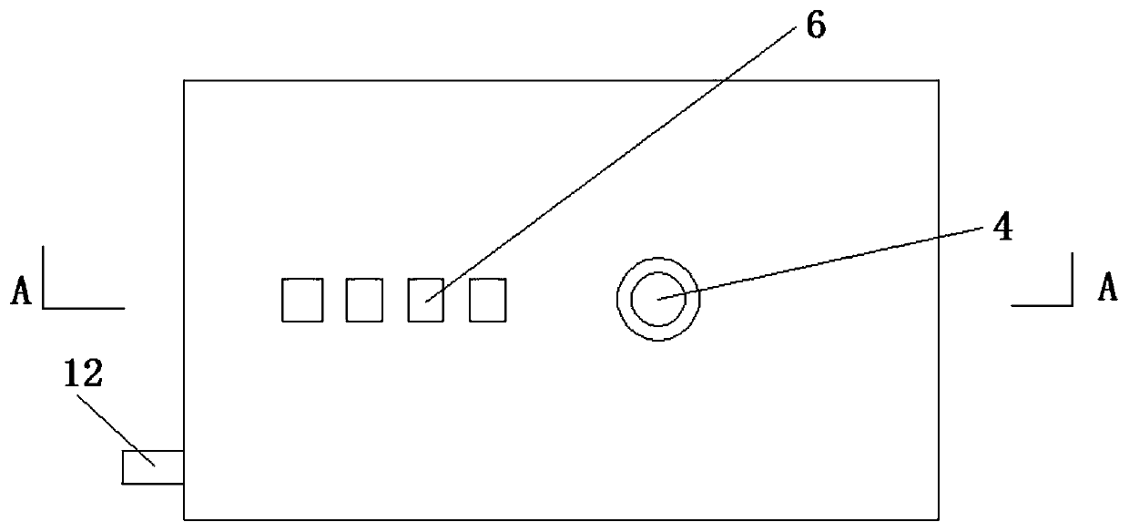
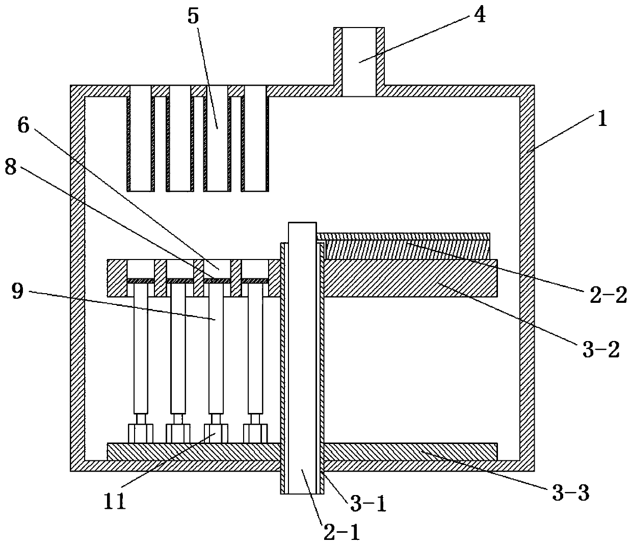
[0040] Step 1. On the 4 forming areas 6 of the disc table 3-2 of the disc rotary multi-channel electron beam rapid prototyping equipment, respectively place 4 titanium part models correspondingly, the size of which is 10mm×10mm×10mm (length × width × height), and then use the layered software Build Assembler to slice the four titanium part models and import the obtained slice data into the computer 13 of the control system of the disc-rotating multi-channel electron beam rapid prototyping equipment; The four forming areas 6 are arranged at equal intervals of 50mm along the radial direction of the disc table 3-2; the slice thicknesses of the four titanium part models obtained by slicing are all 200 μm;

[0041] Step 2: Establish a polar coordinate system on the surface of the disk workbench 3-2 through the computer 13, take the center of the disk workbench 3-2 as the polar coordinate orig...

Embodiment 2

[0048] The manufacturing method of the present embodiment comprises the following steps:

[0049] Step 1. Place one Ti part model, one Cu part model, and one Ni part on the four forming areas 6 of the disc table 3-2 of the disc rotary multi-channel electron beam rapid prototyping equipment. model, one Sn part model, the size is 10mm×10mm×10mm (length×width×height), and then use the layering software Build Assembler to slice the above four part models and import the sliced ​​data into the disk In the computer 13 in the control system of the rotary multi-channel electron beam rapid prototyping equipment; the 4 forming areas 6 are arranged at equal intervals of 50mm along the radial direction of the disc table 3-2; the 4 part models are sliced The slice thickness obtained by processing corresponds to 30 μm, 70 μm, 150 μm and 200 μm respectively;

[0050] Step 2: Establish a polar coordinate system on the surface of the disk workbench 3-2 through the computer 13, take the center ...

Embodiment 3

[0057] The manufacturing method of the present embodiment comprises the following steps:

[0058] Step 1. Place one Ti part model, one Cu part model, and one Fe part on the four forming areas 6 of the disc table 3-2 of the disc rotary multi-channel electron beam rapid prototyping equipment. model and one Sn part model, the size of which is 10mm×10mm×10mm (length×width×height), and then use the layering software Build Assembler to slice the above four part models and import the sliced ​​data into the disc In the computer 13 in the control system of the rotary multi-channel electron beam rapid prototyping equipment; the 4 forming areas 6 are arranged at equal intervals of 50mm along the radial direction of the disc table 3-2; the 4 part models are sliced The slice thickness obtained by processing corresponds to 30 μm, 70 μm, 180 μm and 200 μm respectively;

[0059] Step 2: Establish a polar coordinate system on the surface of the disk workbench 3-2 through the computer 13, take...


PUM

PropertyMeasurementUnit
thicknessaaaaaaaaaa

Abstract

The invention discloses a disk rotating multi-channel electron beam rapid prototyping method. The method comprises: 1. placing a three-dimensional part model on a forming area for slicing; 2. establishing a polar coordinate system to determine the position information of the three-dimensional part model ;3. Calculating the scanning trajectory points of the three-dimensional part model; 4. Spreading powder and positioning the forming area; 5. Scanning and melting the powder to obtain a single-layer solid sheet; 6. Resetting the forming area; ~The process in step six enables the single-layer solid sheets on the shaped base to be stacked layer by layer to obtain a three-dimensional part. The present invention accurately determines the position information of two or more three-dimensional part models on the disk worktable by establishing a polar coordinate system on the disk workbench of the disk rotating multi-channel electron beam rapid prototyping equipment, and then performs scanning and melting respectively, At the same time, the rapid prototyping of three-dimensional parts of different materials is realized, and the forming precision of the parts is improved.

Description

technical field [0001] The invention belongs to the technical field of additive manufacturing, and in particular relates to a disk rotating multi-channel electron beam rapid prototyping method. Background technique [0002] Electron beam selective melting technology (Electron Beam Selective Melting, EBSM) and selective laser sintering technology (Selective Laser Sintering, SLS) are two kinds of additive manufacturing technologies widely used at present. Hardware control technology can directly convert 3D CAD models into entities. Theoretically, any heat-bonded powder can be used as a raw material for additive manufacturing, such as polymers, ceramics, metal powders, and various composite powder materials. Electron beam selective melting rapid prototyping technology is that the electron beam scans line by line according to the pre-planned path driven by the deflection yoke, melts the laid metal powder, accumulates layer by layer, and manufactures the required metal parts. Th...

Claims


Application Information

Patent Timeline
Patent Type & Authority Patents(China)
IPC IPC(8): B22F3/105B33Y10/00
CPCB33Y10/00B22F10/00B22F10/73B22F10/28B22F10/362B22F12/222B22F12/37B22F10/80Y02P10/25
Inventor 贾亮王建刘楠杨坤杨广宇石英刘海彦
Owner NORTHWEST INSTITUTE FOR NON-FERROUS METAL RESEARCH
Why Eureka
Try Eureka