Decorative curtain wall structure

A technology of curtain wall and power parts, applied in the direction of walls, building components, building structures, etc., can solve the problems of thieves, high-rise unsafe, troublesome, etc., to achieve the effect of improving service life, no theft and safety hazards

Active Publication Date: 2019-07-05
BOZHOU VOCATIONAL & TECHNICAL COLLEGE
View PDF5 Cites 1 Cited by
  • Summary
  • Abstract
  • Description
  • Claims
  • Application Information

AI Technical Summary

Problems solved by technology

However, the glass curtain wall in the traditional technology is ventilated by opening windows, central air conditioners or exhaust fans. The first one needs to be manually opened, which is more troublesome, and forgetting to close it will easily lead to thieves, and it is not safe for high-rises; and the third need to be driven by power, which is not conducive to energy saving and environmental protection, so it is urgent to change

Method used


Image

  • Decorative curtain wall structure
  • Decorative curtain wall structure
  • Decorative curtain wall structure

Examples


Embodiment 1

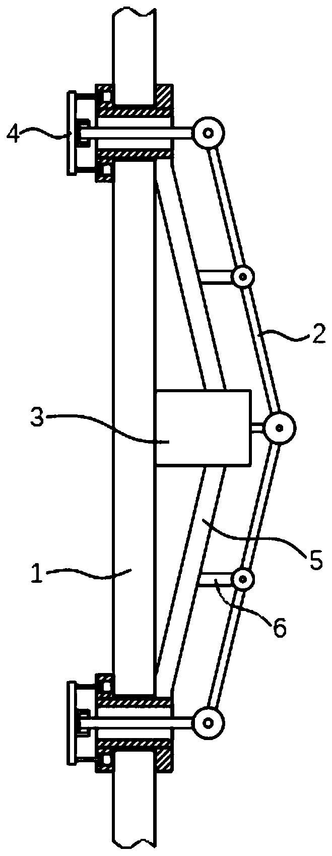
[0028] refer to Figure 1 to Figure 3 , the decorative curtain wall structure includes a power part 3 and a cantilever 5; the cantilever 5 is used to fix the power part 3 and the ventilation fixing part 4.

[0029] The number of the cantilever 5 is multiple, the head of the cantilever 5 is arranged equidistantly along the circumference of the power part 3, and the casing of the cantilever 5 and the power part 3 is integrally formed;

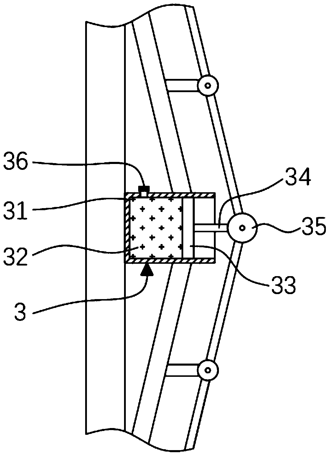
[0030] refer to figure 2 , the power part 3 includes a housing 31, a piston 33, a piston rod 34, a connecting joint 35 and a fluid supply tube 36, and the specific connection methods are as follows:

[0031] The casing 31 is filled with condensate 32, the piston 33 is arranged radially on the inner surface of the casing 31, and the outer diameter of the piston 33 is equal to the inner diameter of the casing 31, and the middle part of the outer side of the piston 33 is fixedly connected with the piston rod 34 , the side of the piston rod 34 awa...

Embodiment 2

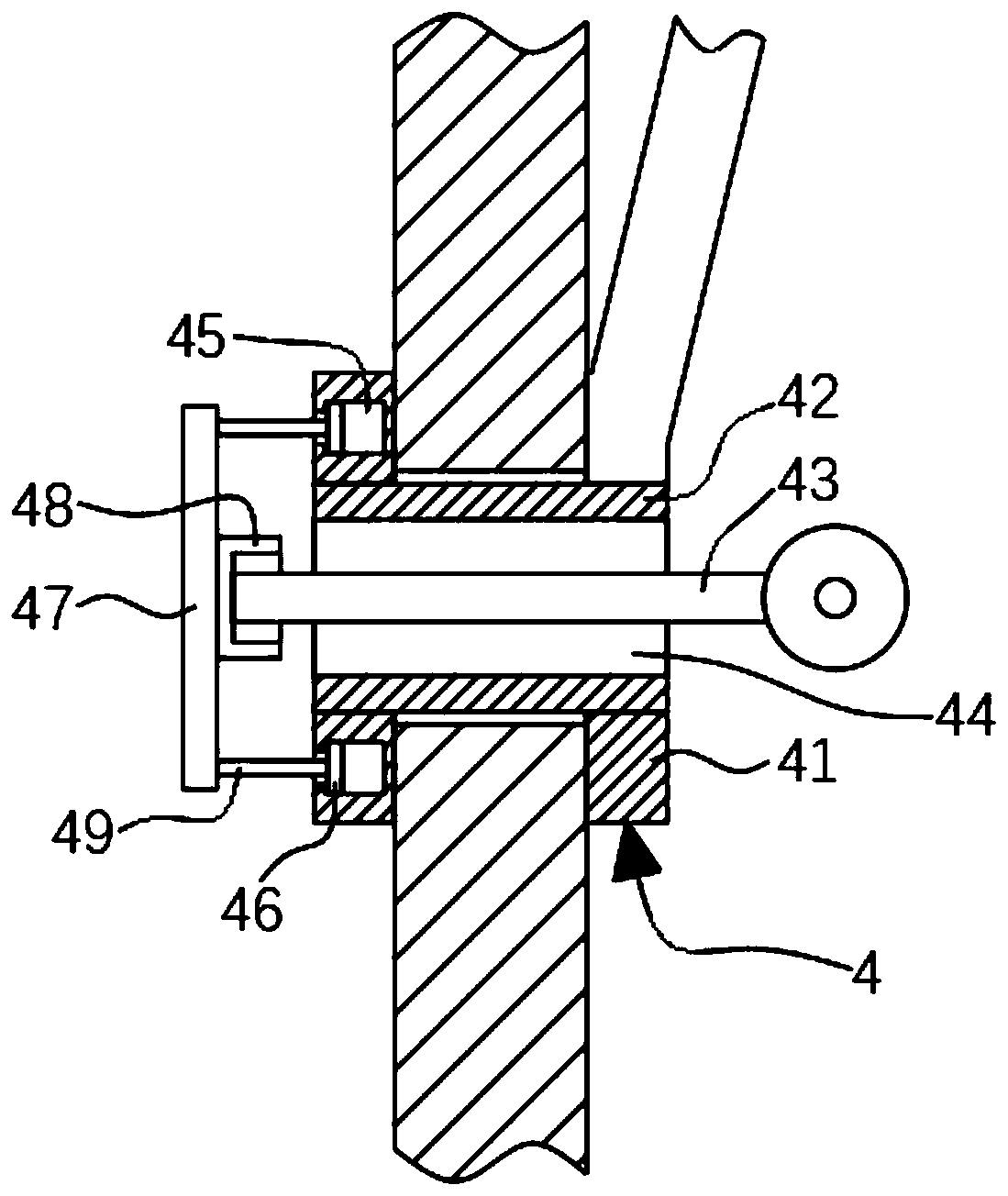
[0042] refer to Figure 4 , this embodiment is further set as follows on the basis of embodiment one:

[0043] The side of the cover 47 close to the ventilation hole 44 is fixedly connected with a sealing member 48. The sealing member 48 is composed of a central round block 482 and a protrusion 481. The inner surface of the ventilation hole 44 is axially provided with a plurality of protrusions to cooperate with the protrusion 481. 422 of the depression.

[0044] Preferably, both the depression 422 and the protrusion 481 adopt an arched structure,

[0045] By setting the recess 422 on the inner wall of the ventilation hole 44, the surface area of ​​the ventilation hole 44 can be increased without increasing the linear distance of the inner wall of the ventilation hole 44, and the effect of thermal stress compensation can be played. The outer side has experienced thermal expansion and contraction for a long time, and the inner wall will inevitably be torn under the action of ...


PUM


Abstract

The invention discloses a decorative curtain wall structure, and relates to the technical field of curtain walls. The decorative curtain wall structure includes a power part and a plurality of cantilevers, the cantilever heads are arranged in the circumferential direction of the power part at equal distance, the cantilevers and a shell of the power part are integrally formed, the tail parts of thecantilevers are fixedly connected with ventilation fixing parts, and the ventilation fixing parts pass through a fixed curtain wall. According to the decorative curtain wall structure, through the power part filled with a condensate, the condensate adopts a solvent with the boiling point being 34-46 DEG C, pentane is taken as an example, the pentane is in the liquid state when the boiling point is less than 36 DEG C, when the outside temperature is increased to the boiling point of the pentane or above, due to the fact that the density of gas is far less than that of liquid, the shell internally expands, thus a piston and a piston column can be driven to move, as the piston column moves, a connecting rod is driven to move according to the lever principle, the other side of the connectingrod moves through a joint lever and separates a blocking cover from a sleeve, and at the moment, the two sides of the sleeve communicate through a ventilation hole to dissipate heat.

Description

technical field [0001] The invention relates to the technical field of curtain walls, in particular to a decorative curtain wall structure. Background technique [0002] Glass curtain wall refers to the building envelope structure or decorative structure that can have a certain displacement capacity relative to the main structure by the supporting structure system and does not share the effect of the main structure. The walls are available in single and double glazing. Glass curtain wall is a kind of beautiful and novel building wall decoration method, and it is a remarkable feature in the era of modernism high-rise buildings. However, the glass curtain wall in the traditional technology is ventilated by opening windows, central air-conditioning or exhaust fans. The first one needs to be manually opened, which is more troublesome, and forgetting to close it will easily lead to thieves, and it is not safe for high-rises; And the third all need to adopt power drive, be unfav...

Claims


Application Information

Patent Timeline
IPC IPC(8): E04B2/88E06B7/02
CPCE04B2/88E06B7/02
Inventor 刘珍徐婧朱钧
Owner BOZHOU VOCATIONAL & TECHNICAL COLLEGE
Why Eureka
Try Eureka