Sealing combined type oil cylinder device

A combined type and oil cylinder technology, which is applied in the direction of fluid pressure actuation device, etc., to achieve excellent sealing performance and solve the effect of oil leakage

Inactive Publication Date: 2019-07-05
谢文俊
View PDF0 Cites 0 Cited by
  • Summary
  • Abstract
  • Description
  • Claims
  • Application Information

AI Technical Summary

Problems solved by technology

However, the problem of sealing is the main problem that it must solve

Method used


Image

  • Sealing combined type oil cylinder device
  • Sealing combined type oil cylinder device
  • Sealing combined type oil cylinder device

Examples


Embodiment Construction

[0014] The present invention will be further described below in conjunction with accompanying drawings and embodiments.

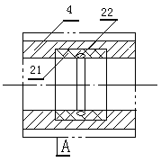
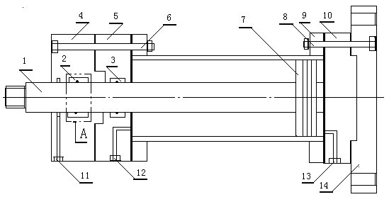
[0015] Embodiment, the present invention relates to a sealed combined oil cylinder device, see the attached figure 1 And attached figure 2 , the piston 7 is fixedly connected with one end of the piston rod 1 and installed coaxially in the oil cylinder 9 and the other end of the piston rod 1 protrudes from the inner hole of the first seal seat 5 and the second seal seat 4 in sequence, the first seal seat 5 The second sealing seat 4 is sealed and fixed with the sealing seat bolt 6 and one end of the oil cylinder 9, and the other end of the oil cylinder 9 is sealed and fixed with the base 10 and the connecting plate 14 in sequence with the base bolt 8, and the first sealing seat 5 and the base 10 are respectively processed. The piston rod end oil inlet hole 12 and the base end oil inlet hole 13 are adapted to the reversing valve, and the first sealing member...


PUM


Abstract

The invention discloses a sealing combined type oil cylinder device. specially, a first sealing part and a second sealing part are installed on a piston rod, an oil drain hole is formed in the outer side of the second sealing part, the first sealing part and the second sealing part are the same in structure, the first sealing part and the second sealing part are both composed of bushes, sealing rings and sealing grooves. The sealing combined type oil cylinder device is excellent in sealing performance and solves the problem of oil leakage of an oil cylinder.

Description

technical field [0001] The invention relates to an oil cylinder device, in particular to an oil cylinder device with a combined seal. Background technique [0002] Hydraulic pressure is widely used in industrial and civil industries due to its large transmission force, easy transmission and configuration. Compared with mechanical rotation and electric transmission, hydraulic transmission has the following advantages: various components of hydraulic transmission can be conveniently and flexibly arranged according to needs; light weight, small size, small motion inertia, fast response speed; convenient manipulation and control, A wide range of stepless speed regulation can be realized; overload protection can be realized automatically. [0003] The hydraulic cylinder device generally uses mineral oil as the working medium, the relative moving surface can be self-lubricated, the service life is long, and it is easy to realize linear motion and machine automation. When the ele...

Claims


Application Information

Patent Timeline
IPC IPC(8): F15B15/14
CPCF15B15/1461
Inventor 谢文俊
Owner 谢文俊
Why Eureka
Try Eureka