Denitration catalyst wear rate testing device and testing method

A technology of denitration catalyst and testing device, which is applied in measurement devices, testing wear resistance, instruments, etc., can solve problems such as uniformity of reduction methods, differences in wear degree in the vertical direction, and obstacles to adding abrasives, so as to improve test results. Comparability, ensure accurate and stable control, avoid the effect of measurement deviation

Pending Publication Date: 2019-07-05
GUODIAN ENVIRONMENTAL PROTECTION RES INST CO LTD
View PDF0 Cites 6 Cited by
  • Summary
  • Abstract
  • Description
  • Claims
  • Application Information

AI Technical Summary

Problems solved by technology

[0005] (1) During the horizontal movement of the abrasive in the air duct with the air flow, due to the action of gravity, it will sink to the bottom of the air duct, resulting in a difference in the degree of wear on the end surface of the denitrification catalyst sample in the vertical direction, which reduces the test process. The uniformity of sample wear in the middle, thus affecting the detection accuracy
[0006] (2) In the conventional method, an anemometer is used to determine the wind speed in the pipe, but because the wind speed on the air pipe section is not uniformly distributed (the wind speed of the pipe core is higher than that of the side wall), it is difficult to achieve accurate and stable control of the test wind speed
[0007] (3) In the conventional method, the front air supply mode of the fan is adopted. During the test, a positive pressure will be formed at the connection point between the abrasive agent discharge port and the air pipe, which will hinder the addition of the abrasive agent and is not conducive to the abrasive agent in the airflow. Accurate and stable control of concentration
Since the judgment of the wear rate is objectively related to the mass difference of the samples before and after the test, and the initial mass of the catalyst samples is not consistent, the calculation method of introducing the initial mass of the sample into the denominator will reduce the uniformity of the method, which is not conducive to the test results of the wear rate among the samples Comparison

Method used


Image

  • Denitration catalyst wear rate testing device and testing method
  • Denitration catalyst wear rate testing device and testing method
  • Denitration catalyst wear rate testing device and testing method

Examples


Embodiment

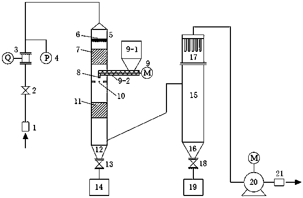
[0030] like figure 1 As shown, a denitrification catalyst wear rate test device in this embodiment includes an air inlet, a wear chamber 5, a wear agent feeder 9, a settling chamber 15, and an induced draft fan 20; The duct is connected to the air inlet, and the air inlet is provided with an air inlet filter 1, and the inlet air duct is provided with an inlet valve 2, a vortex street gas flow meter 3 and a gas pressure gauge 4; the air flows into the intake air from the air inlet filter 1 After the air duct passes through the inlet valve 2, the air flow is measured by the vortex street gas flow meter 3, and the static pressure of the air in the air duct is monitored by the gas pressure gauge 4.

[0031] A rectification grid 6, a comparison sample 7 and a test sample 11 are arranged in the wear chamber 5 in order from top to bottom. After the air enters the wear chamber 5, it first passes through the rectification grille 6 to improve the uniformity of the flow field on the flo...


PUM

PropertyMeasurementUnit
particle size (mesh)aaaaaaaaaa

Abstract

The invention relates to a denitration catalyst wear rate testing device and a testing method. A wear chamber is vertically arranged in the testing device, and the top is connected with an air inlet.A first hopper is arranged at the bottom. A denitration catalyst comprises a test sample and a comparison sample. The comparison sample and the test sample are arranged in the wear chamber, and are arranged from top to bottom along the axis of the wear chamber. The discharge port of a wear agent feeder is arranged on the inner axis of the wear chamber and is located between the comparison sample and the test sample. The lower part of the wear chamber is connected with the middle of a sedimentation chamber through a connecting air duct. The joint of the connecting air duct and the wear chamberis located between the test sample and the first hopper. A second hopper is arranged at the bottom of the sedimentation chamber. A bag-type dust collector is arranged at the top. The bag-type dust collector is connected with an induced draft fan. During a test, negative pressure is formed in the device through the rear induced draft fan; the air is driven to flow in the device; the air flows fromthe top to the bottom in the vertical direction in the wear chamber; and the wear rate of the denitration catalyst is accurately tested.

Description

technical field [0001] The invention relates to a test device and a test method for the wear rate of a denitrification catalyst, and belongs to the technical field of coal-fired air pollutant prevention and monitoring. Background technique [0002] In recent years, my country's control indicators for the emission of nitrogen oxides from thermal power plants have become increasingly strict, and thermal power companies have also paid more and more attention to the quality supervision and management of SCR flue gas denitrification systems, especially the denitrification catalysts as the core components. In coal-fired power plants, the denitrification catalyst is usually arranged in a high-dust arrangement (arranged before the dust collector), and is in direct contact with the dust-laden flue gas. Under the long-term erosion of high-speed flue gas and dust, the denitrification catalyst is prone to wear and tear, leading to failure, perforation or even collapse accidents, directl...

Claims


Application Information

Patent Timeline
Patent Type & Authority Applications(China)
IPC IPC(8): G01N3/56
CPCG01N3/567G01N2203/0676
Inventor 姚杰庄柯侯深肖正雨沙柯燃
Owner GUODIAN ENVIRONMENTAL PROTECTION RES INST CO LTD
Why Eureka
Try Eureka