Low-power-consumption control method, device and system and storage medium

A control method and low-power technology, applied in the fields of instruments, electrical digital data processing, digital data processing components, etc., can solve the problems of limited reduction of system power consumption, short wake-up time, poor system real-time performance, etc., to avoid Frequent switching, avoid time error, ensure the effect of accuracy

Pending Publication Date: 2019-07-05
CHINA MOBILE M2M +1
View PDF14 Cites 14 Cited by
  • Summary
  • Abstract
  • Description
  • Claims
  • Application Information

AI Technical Summary

Problems solved by technology

However, a defect of using such a wake-up mechanism is that it is difficult to reasonably determine the wake-up time corresponding to the periodic wake-up of the timer. If it is too long, it will cause poor real-time performance of the system and affect the normal operation of the business process. In order to avoid affecting the normal processing of business processes, the wake-up time is usually set to be short, resulting in the need to frequently switch between low-power mode and working mode. Therefore, the system power consumption Reduced effect is limited

Method used


Image

  • Low-power-consumption control method, device and system and storage medium
  • Low-power-consumption control method, device and system and storage medium
  • Low-power-consumption control method, device and system and storage medium

Examples


Embodiment 1

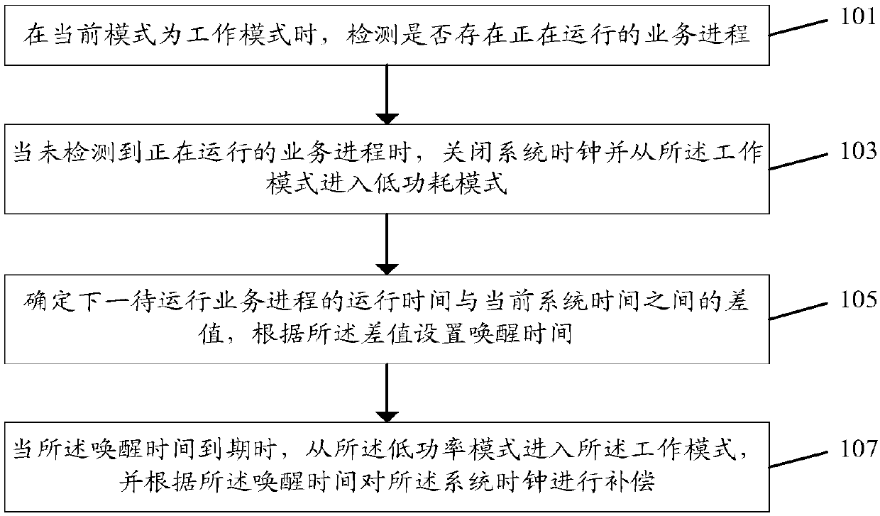
[0120] Figure 4 It is a sequence diagram of the multi-process dynamic wake-up mechanism described in Embodiment 1 of the present invention, wherein process A and process B are business processes, process A and process B run alternately periodically, and the horizontal axis is the time axis.

[0121] like Figure 4 As shown, there is a period of idle time between the first process A and process B, which is "idle 1". This idle time is used to run the daemon process, and the main controller is triggered to enter the low power consumption mode through the daemon process. After the main controller runs process A, it enters "idle 1". At this time, the system clock is turned off, and the time of the system clock at this time is recorded as T1. Calculate how long the running time T2 of running process B is from the current system time T1, that is, T2-T1=X, and take X time as the wake-up time, that is, the interrupt trigger time of the wake-up timer; after waiting for X time, wake up...

Embodiment 2

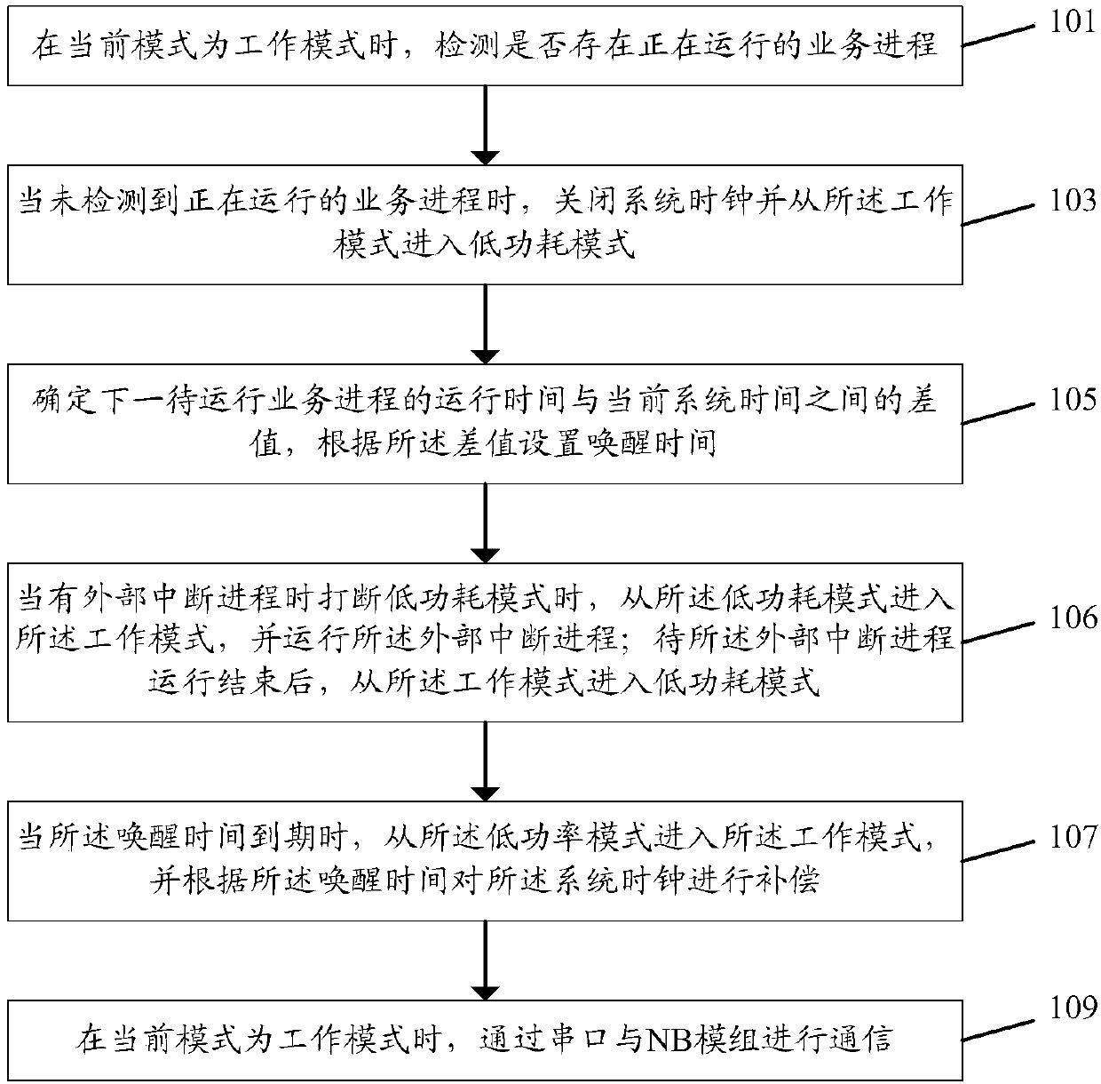
[0125] Figure 5 It is a timing diagram of the multi-process dynamic wake-up mechanism described in Embodiment 2 of the present invention, wherein process A and process B are business processes, process C is an external interrupt process, process A and process B run alternately periodically, and the horizontal axis is the time axis.

[0126] like Figure 5As shown, there is a period of idle time between the first process A and process B, which is "idle 1". This idle time is used to run the daemon process, and the main controller is triggered to enter the low power consumption mode through the daemon process. After the main controller finishes running process A, it enters "idle 1". At this time, turn off the system clock, record the time of the system clock at this time as T1, and enter the starting moment of "idle 1" in the daemon process , calculate how long the running time T2 of the running process B is from the current system time T1, that is, T2-T1=X, take the X time as ...


PUM


Abstract

The embodiment of the invention discloses a low-power-consumption control method which comprises the following steps: when a current mode is a working mode, detecting whether a running service processexists or not; when the running service process is not detected, closing a system clock and entering a low-power-consumption mode from the working mode; determining a difference value between the operation time of the next to-be-operated business process and the current system time, and setting wake-up time according to the difference value; and when the wake-up time expires, entering the workingmode from the low power consumption mode, and compensating the system clock according to the wake-up time. The embodiment of the invention further discloses a low-power-consumption control device andsystem and a computer readable storage medium.

Description

technical field [0001] The present invention relates to the technical field of Internet of Things and embedded industrial control technology, in particular to a low power consumption control method, device, system and storage medium. Background technique [0002] Narrow Band Internet of Things (NB-IoT, Narrow Band Internet of Tings) is an emerging technology in the field of Internet of Things. NB-IoT supports the cellular data connection of low-power devices in the wide area network, also known as low-power wide area network (LPWA); NB-IoT supports high-efficiency connection of devices with long standby time and high network connection requirements; NB-IoT devices Battery life can be increased to at least 10 years, while still providing very comprehensive indoor cellular data connection coverage. Therefore, NB-IoT has broad application prospects. [0003] With the promotion of NB-IOT technology, domestic operators are deploying NB networks on a large scale, and more and mo...

Claims


Application Information

Patent Timeline
Patent Type & Authority Applications(China)
IPC IPC(8): G06F1/3228G06F1/329
CPCG06F1/3228G06F1/329
Inventor 杨燕鎏周家绪李琛
Owner CHINA MOBILE M2M
Why Eureka
Try Eureka