Battery pack hot plug protection circuit and method

A protection circuit, hot-swap technology, applied in the field of electronics, can solve problems such as overvoltage, overcurrent, negative pressure, etc., achieve good switching speed and power consumption, reduce system costs, and facilitate component stocking.

Pending Publication Date: 2019-07-05
HANGZHOU BMSER TECH
0 Cites 0 Cited by

AI-Extracted Technical Summary

Problems solved by technology

[0004] The purpose of the present invention is to provide a battery pack hot-swappable protection circuit and protection method, which a...

Method used

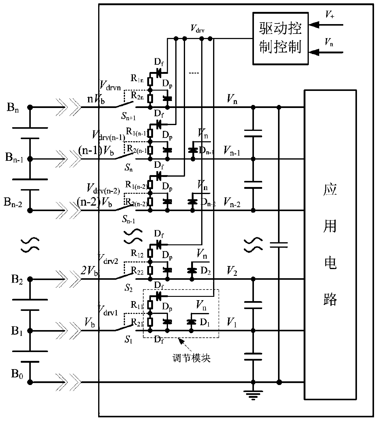
As shown in Figure 2, schematic diagram of the battery pack hot-swappable protection circuit schematic diagram of the present invention is illustrated, and the battery pack realizes plugging and unplugging with the back-end application circuit by the hot-swap protection circuit, to solve the problem of battery pack and application circuit Circuit reliability issues during hot swapping. The battery pack includes a plurality of batteries connected in series, and the hot-swap protection circuit includes a plurality of branches corresponding to the positive and negative poles of each battery. There is no need to connect the switching tubes in series), the driving of all branches is controlled by the first control signal Vdrv, and the first control signal Vdrv changes in real time as each switching tube is turned on and off. The switch tube may be an active switch type such as a MOS tube, a power transistor, an IGBT, or a GTO, and the switch tube may be a unidirectional switch tube or a bidirectional switch tube. The hot-swap protection circuit further includes a drive control circuit and a plurality of adjustment modules, the drive control circuit outputs the first control signal Vdrv, and each switch tube corresponds to an adjustment module. Each adjustment module includes each adjustment module includes a first resistor R1x, a second resistor R2x (the subscript x is different in different adjustment modules, refer to the reference numerals for details), a first diode Df, a first voltage regulator transistor Dp and The second diode Dx, the first resistor R1x and the first diode Df are connected in series to form a first series circuit, the second resistor R2x and the first voltage regulator tube Dp are connected in parallel to form a first parallel circuit, and the first end of the first series circuit It is connected to the output end of the driving control circuit, the second end thereof is connected to the first end of the first parallel circuit, and the second end of the first parallel circuit i...

Abstract

The invention provides a battery pack hot plug protection circuit and method. The battery pack comprises N series connected batteries, the positive pole of the kth battery is connected to the negativepole of the k+1th battery; the hot plug protection circuit comprises N branches, the kth branch corresponds to the positive pole of the kth battery, the Nth branch corresponds to the positive pole ofthe Nth battery, and each branch is connected in series with a switch tube; a first control signal controls the on and off of the respective switch tubes and changes in real time as each switch tubeis turned on and off, the difference between the first control signal and the voltage of the output end of each branch is divided to drive the on and off of the switch tubes on corresponding branches;the kth branch is preferentially turned on than the k+1th branch, and the kth branch is turned off slower than the k+1th branch, wherein k is greater than or equal to 1, and +1 is greater than k andless than or equal to N. The battery pack hot plug protection circuit and method completely suppress surge current and surge voltage and improve circuit performance.

Application Domain

Technology Topic

Surge voltageElectrical battery +5

Image

  • Battery pack hot plug protection circuit and method
  • Battery pack hot plug protection circuit and method
  • Battery pack hot plug protection circuit and method

Examples

  • Experimental program(1)

Example Embodiment

[0023] The preferred embodiments of the present invention will be described in detail below with reference to the accompanying drawings, but the present invention is not limited to these embodiments. The present invention covers any alternatives, modifications, equivalent methods and arrangements made within the spirit and scope of the present invention.
[0024] In order to give the public a thorough understanding of the present invention, specific details are described in detail in the following preferred embodiments of the present invention, and those skilled in the art can fully understand the present invention without the description of these details.
[0025] The invention is described in more detail by way of example in the following paragraphs with reference to the accompanying drawings. It should be noted that the accompanying drawings are all in a relatively simplified form and in an inaccurate scale, and are only used to facilitate and clearly assist in explaining the purpose of the embodiments of the present invention.
[0026] like figure 2 As shown in the figure, the schematic diagram of the hot-swap protection circuit of the battery pack of the present invention is shown. circuit reliability issues. The battery pack includes a plurality of batteries connected in series, the hot-swap protection circuit includes a plurality of branches corresponding to the positive and negative poles of each battery, and each branch is connected in series with a switch tube (for the road where the output end is grounded). No need to connect switches in series), all branches are driven on and off by a first control signal Vdrv, which changes in real time with the on and off of each switch. The switch tube may be an active switch type such as a MOS tube, a power triode, IGBT, GTO, etc. The switch tube may be a unidirectional switch tube or a bidirectional switch tube. The hot-plug protection circuit further includes a drive control circuit and a plurality of adjustment modules, the drive control circuit outputs the first control signal Vdrv, and each switch tube corresponds to one adjustment module. Each adjustment module includes a first resistor R1x, a second resistor R2x (the subscript x is different in different adjustment modules, see reference numerals for details), a first diode Df, a first voltage regulator Dp and The second diode Dx, the first resistor R1x and the first diode Df are connected in series to form a first series circuit, the second resistor R2x and the first voltage regulator Dp are connected in parallel to form a first parallel circuit, and the first end of the first series circuit The output end of the driving control circuit is connected, the second end thereof is connected to the first end of the first parallel circuit, and the second end of the first parallel circuit is connected to the output end of the regulating module. The anode of the second diode Dx is connected to the output terminal of the corresponding branch, and the cathode is connected to the high potential terminal of the battery pack voltage, that is, the output terminal of the highest branch. Zener diode Dp is used to clamp the driving voltage to prevent the switching tube from being damaged due to too high driving voltage. The diode Df is used to isolate the drive of each branch switch to prevent the driving voltage of each branch from interfering with each other, or to form an interference loop, causing the hot-swap protection circuit to fail. At the same time, when one or several branches fail, Df can isolate these damaged branches without affecting the operation of other branches.
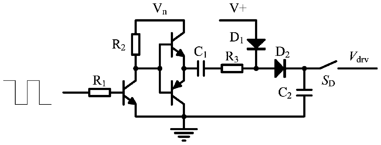
[0027] like image 3 As shown, the principle diagram of the drive control circuit of the present invention is shown, and the drive control circuit is a drive control circuit, and the drive control circuit includes a resistor R1, a resistor R2, a resistor R3, and transistors Q1, Q2, Q3 (Q1, Q2 are NPN type, Q3 is PNP type), capacitors C1, C2, diodes D1, D2 and switch S D The first end of the resistor R1 receives the square wave signal Tp, the second end of the resistor R1 is connected to the base of the transistor Q1, the emitter of the transistor Q1 is grounded, and the collector is connected to the first end of the resistor R2 and the bases of the transistors Q2 and Q3. The second end of the resistor R2 and the collector of the transistor Q2 receive the highest branch output voltage Vn, the emitter of the transistor Q2 is connected to the emitter of the transistor Q3 and the first end of the capacitor C1, and the collector of the transistor Q3 is grounded. The second end of capacitor C1 is connected to the first end of resistor R3, the second end of resistor R3 is connected to the cathode of diode D1 and the anode of diode D2, and the anode of diode D1 receives a given voltage V + , the cathode of diode D2 is connected to the first end of capacitor C2, the second end of capacitor C2 is grounded, switch SD The first terminal is connected to the common terminal of the capacitor C2 and the diode D2, and the second terminal outputs the first control signal Vdrv. Voltage V + The voltage value satisfies the relationship: Vb+Vth + -2V D <2Vb+Vth, where: Vb is the voltage of the single cell in the series battery pack, Vth is the threshold voltage of the switch (S1, S2...Sn), V D It is the forward voltage drop of diodes D1 and D2 in the drive control circuit. switch S D When closed, the output voltage of the drive control circuit Vdrv≈V n +V + -2V D , is no longer a fixed voltage signal, but a changing voltage consisting of n+1 steps.
[0028] During the time when two adjacent switches are turned on, there are two delay times, which are the rise time of the output voltage of the drive control circuit and the rise time of the drive voltage of the switch tube. Among them, the rise time of the output voltage of the drive control circuit is determined by the input square wave frequency, current limiting resistor R3, capacitors C1 and C2 and other parameters. For example, increasing the resistance value of R3, the capacitance value of C2, and reducing the square wave frequency can extend the drive control circuit. The rise time of the output voltage, on the contrary, can shorten the rise time of the output voltage. The rise time of the switch drive voltage is determined by the resistance values ​​R1x, R2x, the first control signal Vdrv and the parasitic capacitance Ciss of the switch. Since the parasitic capacitance is not adjustable after the switch is selected, Vdrv is determined by the rise time of the drive control circuit, so The adjustment of the rise time of the driving voltage of the switch tube can be realized by adjusting the resistance values ​​R1x and R2x.
[0029] like Figure 4 As shown, the waveform diagram of the first control signal during the turn-on process of the switch tube is illustrated, that is, the relative time relationship between the first control signal and the drive voltage of each branch switch tube during the turn-on process. At time t0, Image 6 switch S in D Turn on and output a square wave signal to R1. At this time V n =0V, drive output voltage Vdrv=V + -2V D. Since Vb+Vth Vth, Vdrv2=Vdrv-2Vb figure 2 During the conduction of diode D1, Vn follows V1 and rises to Vb, and then due to the action of the drive control circuit, the first control signal Vdrv increases to Vdrv=V + +Vb-2V D , since Vdrv2=Vdrv-2Vb=V + -Vb-2V DVth, Vdrv3=Vdrv-3Vb=V + -2Vb-2V D + +2Vb-2V D , since Vdrv3=Vdrv-3Vb=V + -Vb-2V DVth, Vdrv4=Vdrv-4Vb=V + -2Vb-2V D
[0030] like Figure 5 As shown in the figure, the waveform diagram of the first control signal during the turn-off process of the switch tube is shown. At time t0, the switch is turned off image 3 switch S in D , and close the square wave signal output (maintain high level, or low level), at this time Vdrv=V + -2V D +nVb. Since the output voltage of each branch satisfies VBn>VB(n-1)>...>VB2>VB1, and Vdrv is shared by each channel, so in the process of Vdrv falling, it must be the Sn switch that drives the first (t1 time) is lower than the start-up threshold, that is, the first one is turned off, the Sn-1 switch is turned off at the second (time t2), and so on. It can be seen from the above analysis that due to the sequential turn-on and turn-off of each branch of the switch matrix, the system will not have a negative voltage phenomenon during the entire insertion and removal process. Adjusting the rise rate of the output voltage of the drive control circuit (square wave frequency, current limiting resistor R3, capacitors C1 and C2) can adjust the overall turn-on speed of the switch matrix, and adjusting the drive resistance values ​​R1x and R2x can adjust the switching speed of each branch respectively. , thereby suppressing surge voltage and surge current.
[0031] like Image 6 As shown, another embodiment schematic diagram of the switch tube of the battery pack hot swap protection circuit of the present invention is shown. The switch tube is a bidirectional switch tube, which can control the current direction from the battery to the application circuit, and can also control the application circuit to the The direction of current flow in the battery. The bidirectional switch tubes are two connected switch tubes. The driving voltages of the two switch tubes are obtained by dividing the voltage of the voltage divider resistors R1x and R2x. The sources of the two switch tubes are connected, and the drain of one switch tube is connected to Bn. terminal, the drain of the other switch is connected to the application circuit.
[0032] Although the embodiments are described and described separately above, some common technologies are involved, and in the opinion of those of ordinary skill in the art, they can be replaced and integrated between the embodiments. Reference is made to another example described.
[0033] The above-mentioned embodiments do not constitute a limitation on the protection scope of the technical solution. Any modifications, equivalent replacements and improvements made within the spirit and principles of the above-mentioned embodiments shall be included within the protection scope of this technical solution.

PUM

no PUM

Description & Claims & Application Information

We can also present the details of the Description, Claims and Application information to help users get a comprehensive understanding of the technical details of the patent, such as background art, summary of invention, brief description of drawings, description of embodiments, and other original content. On the other hand, users can also determine the specific scope of protection of the technology through the list of claims; as well as understand the changes in the life cycle of the technology with the presentation of the patent timeline. Login to view more.

Similar technology patents

Classification and recommendation of technical efficacy words

  • Reduce system cost
  • Large adjustable range

Data restoring and synchronizing method based on log snapshot

Owner:INSPUR TIANYUAN COMM INFORMATION SYST CO LTD

System for camera-based vital sign measurement

InactiveUS20150105670A1Accurate and reliableReduce system costSurgeryPerson identificationRespiratory rateVital Signs Measurement
Owner:KONINKLJIJKE PHILIPS NV

Semi-active type vehicle seat vibration absorbing device with magneto-rheological elastomer

ActiveCN104802680ALarge adjustable rangeGood shock absorption and damping performanceSpringsSeat suspension devicesPower flowSemi active
Owner:BEIHANG UNIV

Reducing valve

Owner:HANGZHOU WORLDWISE VALVE
Why Eureka
Try Eureka