
Heart rate measuring instrument

A detection device and technology of heart rate, applied in the directions of diagnostic recording/measurement, medical science, sensors, etc., can solve the problems of reduced user experience, poor stability of circuit structure, complicated operation, etc., to improve user experience, facilitate user operation, and improve accuracy. degree of effect

Inactive Publication Date: 2019-07-09
JIANGXI UNIV OF TECH
View PDF7 Cites 2 Cited by
  • Summary
  • Abstract
  • Description
  • Claims
  • Application Information

AI Technical Summary

Problems solved by technology

[0003] During the use of the existing heart rate detection device, the user needs to actively trigger the control to collect the user's heart rate, which leads to cumbersome operations for the user and reduces the user experience, and the circuit structure of the existing heart rate detection device is poor in stability during use , which in turn leads to low heart rate detection accuracy and reduces the detection efficiency of the heart rate detection device

Method used


Image

  • Heart rate measuring instrument
  • Heart rate measuring instrument
  • Heart rate measuring instrument

Examples


Embodiment Construction

[0042] In order to make the above objects, features and advantages of the present invention more comprehensible, specific implementations of the present invention will be described in detail below in conjunction with the accompanying drawings. Several embodiments of the invention are shown in the drawings. However, the present invention can be embodied in many different forms and is not limited to the embodiments described herein. Rather, these embodiments are provided so that the disclosure of the present invention will be thorough and complete.

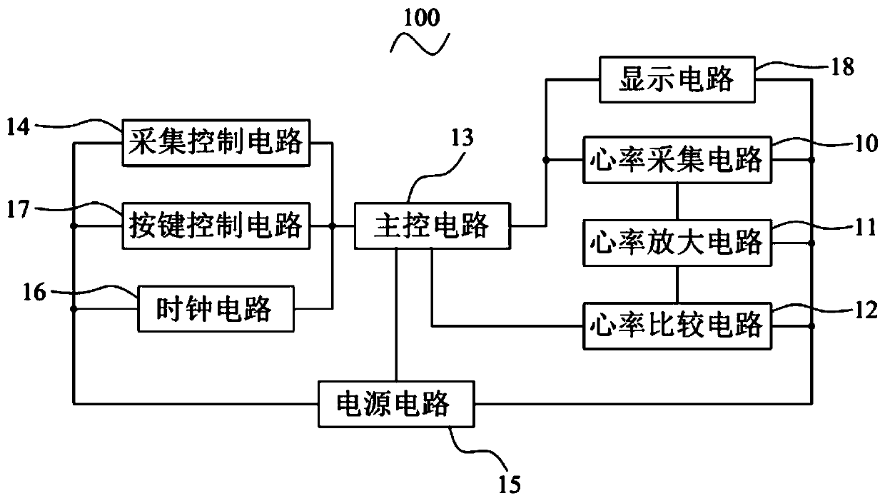
[0043] see figure 1 , the first embodiment of the present invention provides a heart rate detection device 100, including a heart rate acquisition circuit 10, a heart rate amplification circuit 11, a heart rate comparison circuit 12, a main control circuit 13 and an acquisition control circuit 14, wherein:

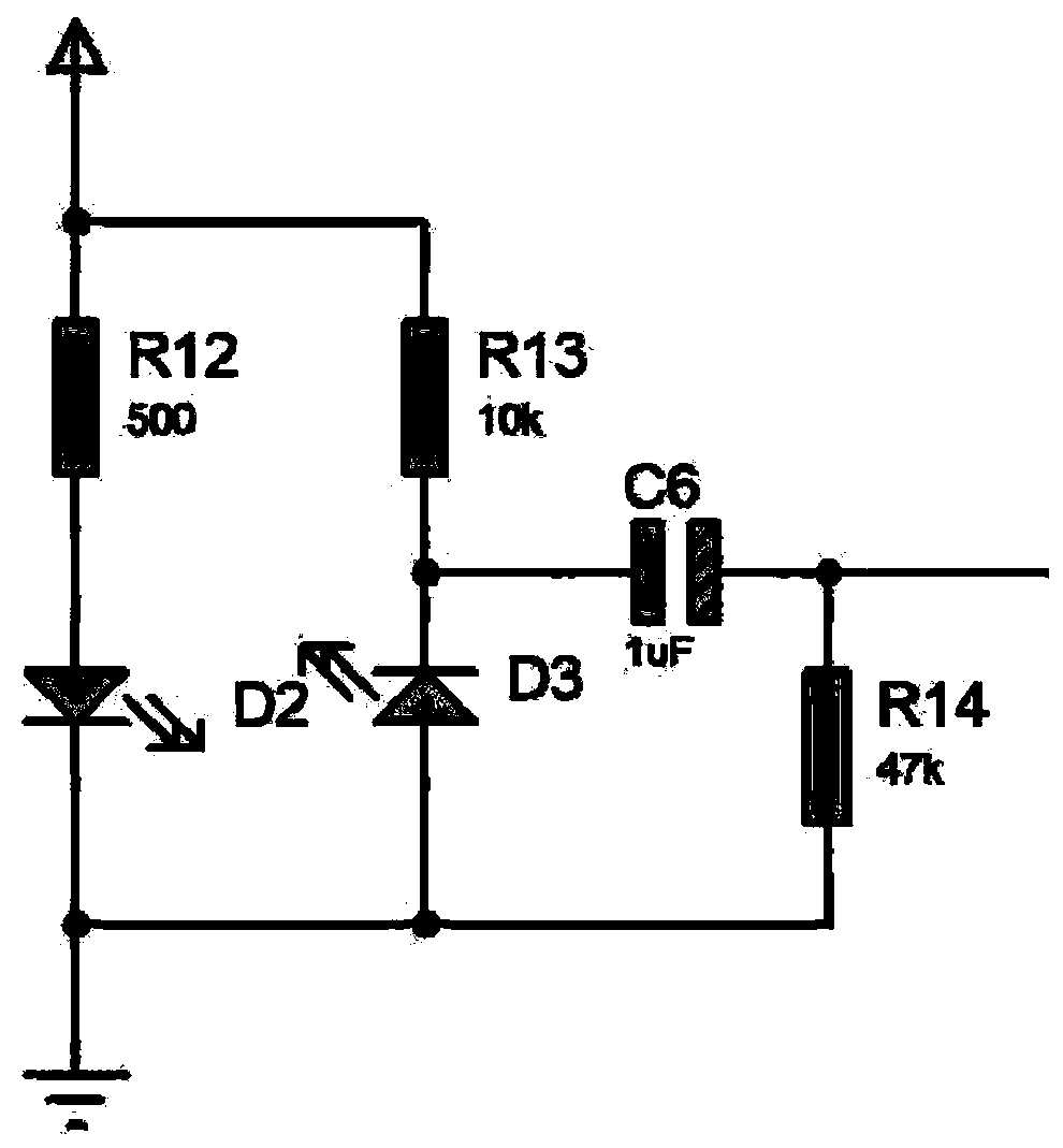
[0044] The heart rate acquisition circuit 10 includes an infrared emitting tube D2 and an infrared receiving tube D3, and th...


PUM


Abstract

The invention provides a heart rate measuring instrument comprising a heart rate acquisition circuit, a heart rate amplification circuit, a heart rate comparison circuit, a main control circuit and anacquisition control circuit. The heart rate acquisition circuit includes an infrared transmitting tube and an infrared receiving tube; the heart rate amplification circuit includes a signal amplifier; the heart rate comparison circuit includes a signal comparator; the main control circuit includes a main control chip; the acquisition control circuit includes a pyroelectric infrared sensor. Through the design of an acquisition control module, the acquisition of whether or not to trigger the heart rate is automatically carried out by using the pyroelectric infrared sensor, and the trigger control of the heart rate acquisition is not required, which facilitates the operation of a user and improves the user experience; through the design of the heart rate acquisition circuit, the heart rate amplification circuit and the heart rate comparison circuit, acquisition, amplification and comparison of the heart rate can be effectively and automatically carried out, the stability of the whole circuit structure is effectively improved, and the accuracy of heat rate measuring is improved.

Description

technical field [0001] The invention relates to the technical field of heart rate detection, in particular to a heart rate detection device. Background technique [0002] With the rapid development of the economy, people's requirements for the quality of life are also rapidly increasing, and the health problems are getting more and more attention from the society, and there is a great relationship between physical examination and physical health, which is to understand the physical health status the most direct means. As one of the important indicators reflecting the health status of the human body, the detection of heart rate is particularly important. Therefore, heart rate detection equipment has become an indispensable daily necessities in family life. [0003] During the use of the existing heart rate detection device, the user needs to actively trigger the control to collect the user's heart rate, which leads to cumbersome operations for the user and reduces the user e...

Claims


Application Information

Patent Timeline
IPC IPC(8): A61B5/0245
CPCA61B5/02444A61B5/0245
Inventor 孟蕾
Owner JIANGXI UNIV OF TECH
Learn More