Rotatable overflow pipe cyclone separator and separation equipment

A technology of cyclone separator and overflow pipe, which is applied in the direction of swirl devices and devices whose axial direction can be reversed, can solve the problems of reduced air flow velocity, high pressure drop of cyclone separator, and high energy consumption, and achieve Promotes gas flow, suppresses short-circuit flow, and reduces pressure drop

Pending Publication Date: 2019-07-09
兰州云式环境科技有限公司
View PDF0 Cites 1 Cited by
  • Summary
  • Abstract
  • Description
  • Claims
  • Application Information

AI Technical Summary

Problems solved by technology

However, the air flow in the conical cylinder is large, and the moment it enters the air outlet pipe, it is easy to form a short-circuit flow. At the same time, after the gas enters the air outlet pipe, the airflow velocity decreases and flows downward. In the prior art, the overflow pipe can be rotated to form a cyclone Separator high pressure drop, resulting in high energy consumption

Method used


Image

  • Rotatable overflow pipe cyclone separator and separation equipment
  • Rotatable overflow pipe cyclone separator and separation equipment
  • Rotatable overflow pipe cyclone separator and separation equipment

Examples


Embodiment 1

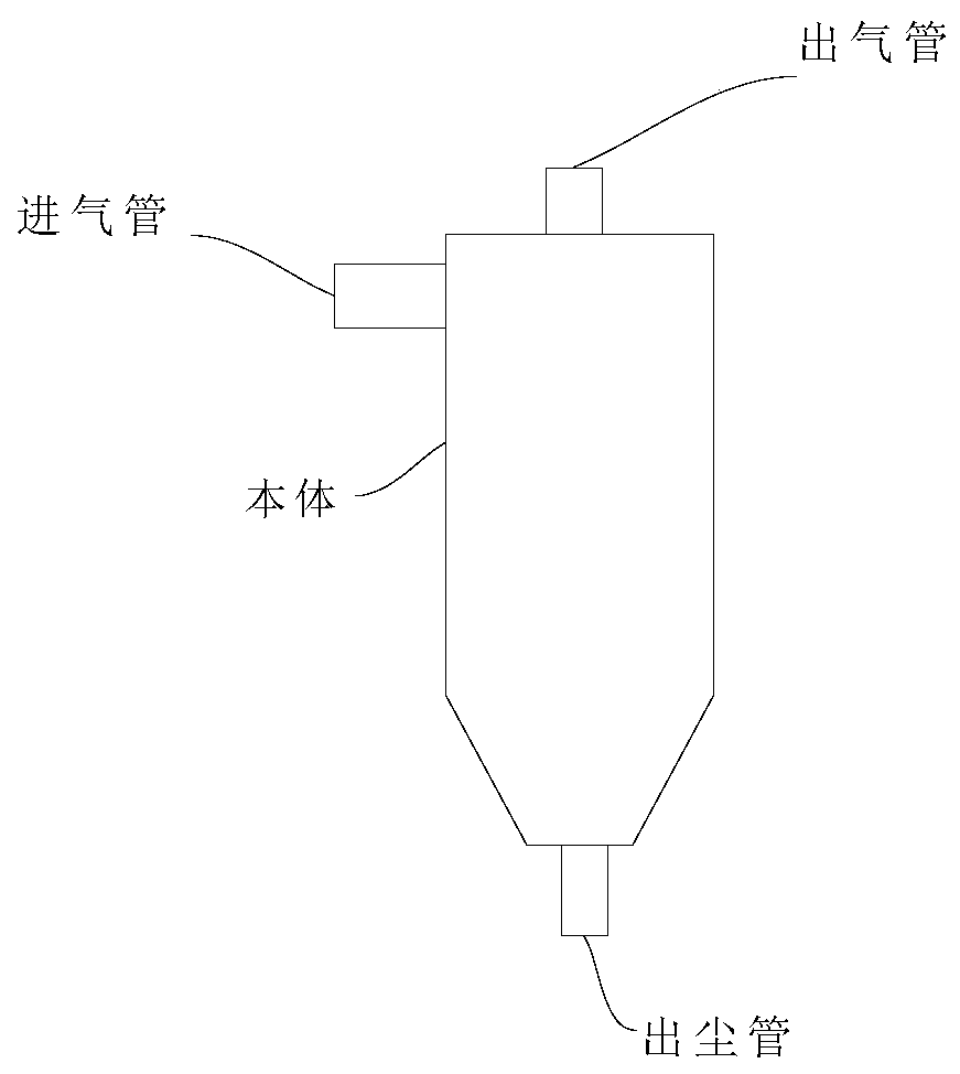
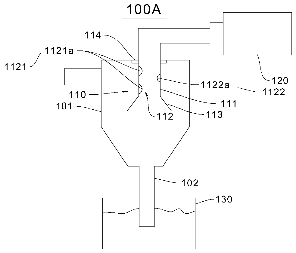
[0032] see figure 2 , this embodiment provides a rotatable overflow pipe cyclone separator 100A, which includes a separator body 101, the separator body 101 is the structure of a rotatable overflow pipe cyclone separator in the prior art, such as a conical cylinder body, the gas to be separated forms a swirling airflow inside the separator body 101 to achieve gas-solid or liquid-solid separation.

[0033] The upper part of the separator body 101 is provided with a gas inlet in the tangential direction of the cylinder, and the top of the separator body 101 is provided with a gas outlet. The separator body 101 includes a dust outlet pipe 102, and the dust outlet pipe 102 is arranged at the bottom of the separator body 101. And connected with the separator body 101.

[0034] It should be noted that the tangential direction involved in the present invention refers to the horizontal direction perpendicular to the axis centerline of the separator body 101. The gas inlet and gas ou...

Embodiment 2

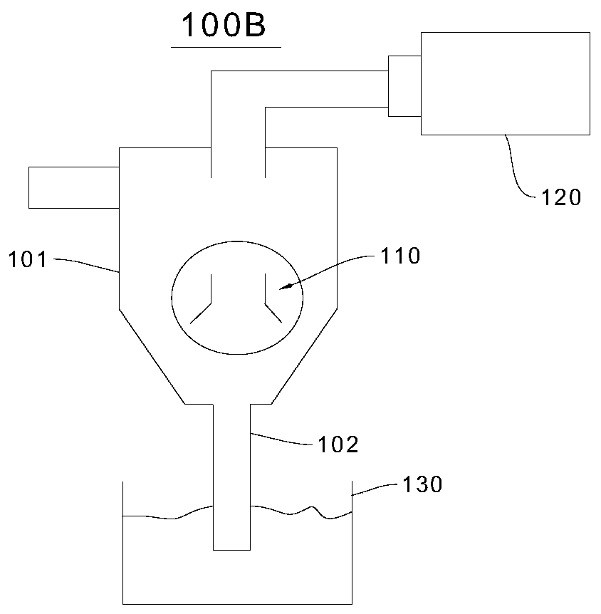
[0048] see image 3 The structure of the rotatable overflow pipe cyclone separator 100B provided in this embodiment is basically the same as that of the rotatable overflow pipe cyclone separator 100A provided in Embodiment 1, except that the location and structure of the flow suppression device 110 are added.

[0049] Specifically, the flow suppression device 110 is arranged in the middle of the separator body 101 and is connected to the separator body 101. Furthermore, the rotating tube 111 and the expansion piece 113 are both arranged in the middle of the separator body 101, and the rotating tube 111 can be opposite to the separator. The main body 101 rotates, and the extension piece 113 is connected with the separator main body 101 . It should be noted that since the flow suppressing device 110 is arranged in the middle of the separator body 101 in this embodiment, in order to ensure that the first rotating device 112 acts on the internally swirling gas, the rotating pipe 1...


PUM


Abstract

The invention relates to the field of separation devices, in particular to a rotatable overflow pipe cyclone separator and separation equipment. The rotatable overflow pipe cyclone separator comprisesa separator body and a flow suppression device, wherein the flow suppression device promotes the formation of rotating movement of gas to be separated and suppresses the appearance of short-circuit flow in internal swirl flow. The flow suppression device is arranged in the separator body and connected with the separator body. The flow suppression device comprises a rotating pipe which can rotaterelative to the separator body and a first rotating device driving the rotating pipe to rotate. The first rotating device is arranged in the rotating pipe and connected with the rotating pipe. The rotating pipe is arranged in the separator body and connected with the separator body. The flow suppression device can suppress the short-circuit flow, improve the separation efficiency, and reduce the pressure drop of the rotatable overflow pipe cyclone separator.

Description

technical field [0001] The invention relates to the field of separation devices, in particular to a rotatable overflow pipe cyclone separator and separation equipment. Background technique [0002] see figure 1 The main structure of the rotatable overflow pipe cyclone separator is a conical cylinder. A gas inlet pipe is installed in the tangential direction of the upper part of the cylinder. The top of the cylinder is equipped with an outlet pipe inserted into the cylinder to a certain depth. The bottom of the conical cylinder has a fine powder receiving pipe. powder outlet. When the dust-laden airflow enters the rotatable overflow pipe cyclone separator from the intake pipe, the airflow will change from linear motion to circular motion. Most of the swirling air flows along the wall from the cylinder in a spiral downward direction toward the cone. In addition, the particles are thrown towards the wall under the action of centrifugal force. Once the dust particles contact ...

Claims


Application Information

Patent Timeline
IPC IPC(8): B04C5/04B04C5/08B04C5/081B04C5/103B04C5/107B04C5/12B04C5/18B04C5/187
CPCB04C5/04B04C5/08B04C5/081B04C5/103B04C5/107B04C5/12B04C5/18B04C5/187
Inventor 张建峰
Owner 兰州云式环境科技有限公司
Why Eureka
Try Eureka