Intelligent card and working method thereof
A working method and smart card technology, applied in instruments, calculations, record carriers used by machines, etc., can solve problems such as delay and detection errors, and achieve the effect of speeding up detection speed and accuracy.
- Summary
- Abstract
- Description
- Claims
- Application Information
AI Technical Summary
Problems solved by technology
Method used
Image

Examples
Embodiment 1
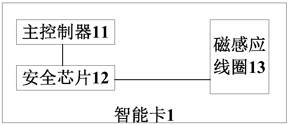
[0038] figure 1 For the schematic structural diagram of the smart card provided in Embodiment 1 of the present invention, please refer to figure 1 , the smart card 1 provided by the present embodiment includes: a main controller 11, a security chip 12 and a magnetic induction coil 13, the main controller 11 is at least electrically connected to the power control pin of the security chip 12, and the security chip 12 is electrically connected to the magnetic induction coil 13 , when the magnetic induction coil 13 is in the magnetic field, the potential of the power control pin is the first potential, and when the magnetic induction coil is not in the magnetic field, the potential of the power control pin is the second potential, and the first potential is different from the second potential; The main controller 11 is used to detect the real-time potential value of the power control pin, and execute corresponding data processing according to the real-time potential value.
[003...
Embodiment 2
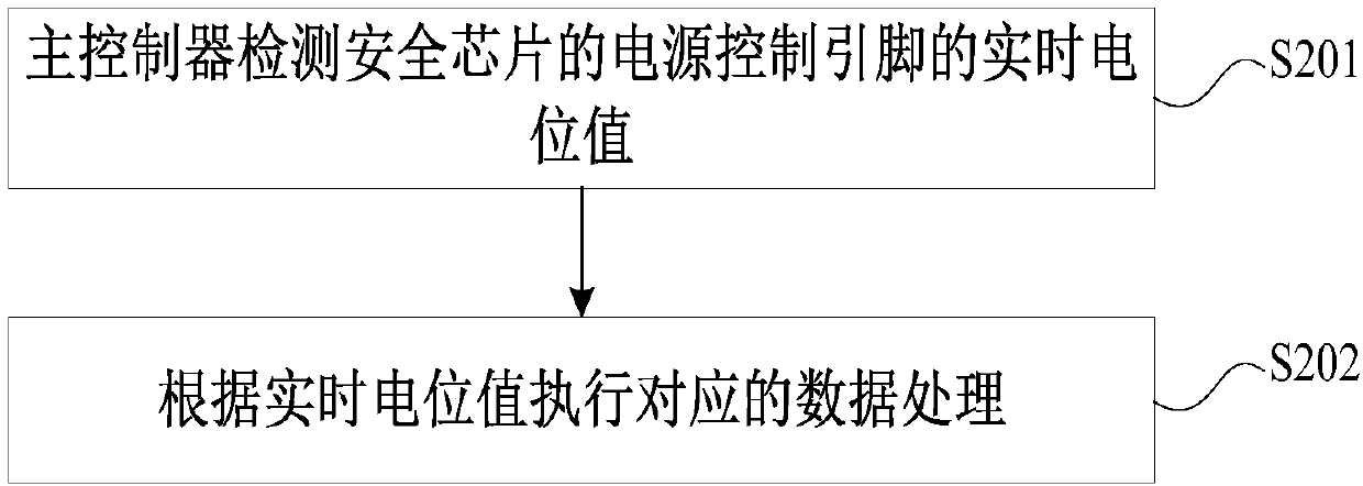
[0045] figure 2 For the flow chart of the smart card working method provided by Embodiment 2 of the present invention, please refer to figure 2 , the smart card working method provided by the present embodiment comprises the following steps:
[0046] S201: The main controller detects the real-time potential value of the power control pin of the security chip; the security chip is electrically connected to the magnetic induction coil, when the magnetic induction coil is in the magnetic field, the potential of the power control pin is the first potential, and when the magnetic induction coil is not in When in the magnetic field, the potential of the power control pin is the second potential, and the first potential is different from the second potential;
[0047] S202: Perform corresponding data processing according to the real-time potential value.
[0048] In some embodiments, step S202 includes: calling a preset corresponding relationship, determining a target application...
Embodiment 3
[0052] In this embodiment, the smart card is described as a payment card such as a bank card as an example.
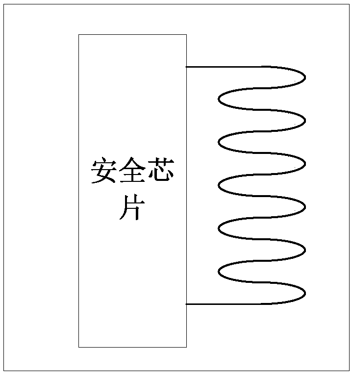
[0053] image 3 For the schematic structural diagram of the smart card provided in Embodiment 3 of the present invention, please refer to image 3 , The smart card provided by this embodiment includes: a security chip and a communication coil (such as a magnetic induction coil), the security chip is provided with a radio frequency module, the security chip is electrically connected to the communication coil, and the security chip stores security data such as user account information.
[0054] Such as Figure 4 As shown, the smart card is close to the card reader, and after being activated by the magnetic signal, it will interact with the card reader to complete the payment. After the smart card is away from the card reader, it will go to sleep. The outer layer program of the credit card payment application involved in the present embodiment is realized in bytecode mo...
PUM
 Abstract
Description
Claims
Application Information
 - R&D
- Intellectual Property
- Life Sciences
- Materials
- Tech Scout
- Unparalleled Data Quality
- Higher Quality Content
- 60% Fewer Hallucinations
Browse by: Latest US Patents, China's latest patents, Technical Efficacy Thesaurus, Application Domain, Technology Topic, Popular Technical Reports.
© 2025 PatSnap. All rights reserved.Legal|Privacy policy|Modern Slavery Act Transparency Statement|Sitemap|About US| Contact US: help@patsnap.com