
Oil-Immersed power transformer based on negative pressure anti-spill filling

A technology for power transformers and transformers, applied in the field of transformers, can solve the problems of transformer oil overflowing and dripping on the surface of the oil conservator, the insulation of transformer oil is reduced, and the transformer oil is mixed into the air, etc., so as to improve construction safety, ensure insulation performance, and improve quality effect

Active Publication Date: 2019-07-09
国网黑龙江省电力有限公司大兴安岭供电公司 +1
View PDF8 Cites 8 Cited by
  • Summary
  • Abstract
  • Description
  • Claims
  • Application Information

AI Technical Summary

Problems solved by technology

[0003] After the transformer has been used for a long time, in order to ensure the stability of the transformer, it is necessary to change the oil of the transformer. When changing the oil, it needs to be replenished from the oil conservator. When filling the transformer oil, the staff needs to carry the barreled transformer oil and climb to the transformer support Then, after opening the transformer sealing bolt, pour the transformer oil into the oil conservator through the funnel. In spring and summer, the surface of the transformer support is wet and slippery, and it is dangerous to climb with a large amount of transformer oil. The medium transformer oil is directly dripped from the filling port and mixed with the residual transformer oil in the oil conservator, which will easily cause the transformer oil in the oil conservator to mix into the air and generate foam. Water molecules in the air will cause the insulation of the transformer oil to decrease, and During the filling process, it is easy to cause the transformer oil to overflow from the funnel and drip onto the surface of the oil conservator. After filling, it needs to be cleaned up, which is complicated to operate.

Method used


Image

  • Oil-Immersed power transformer based on negative pressure anti-spill filling
  • Oil-Immersed power transformer based on negative pressure anti-spill filling
  • Oil-Immersed power transformer based on negative pressure anti-spill filling

Examples


Embodiment

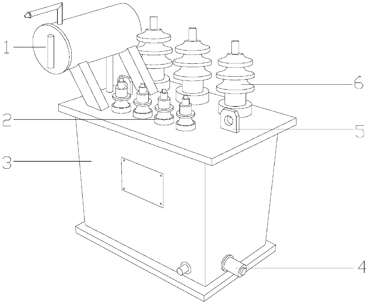
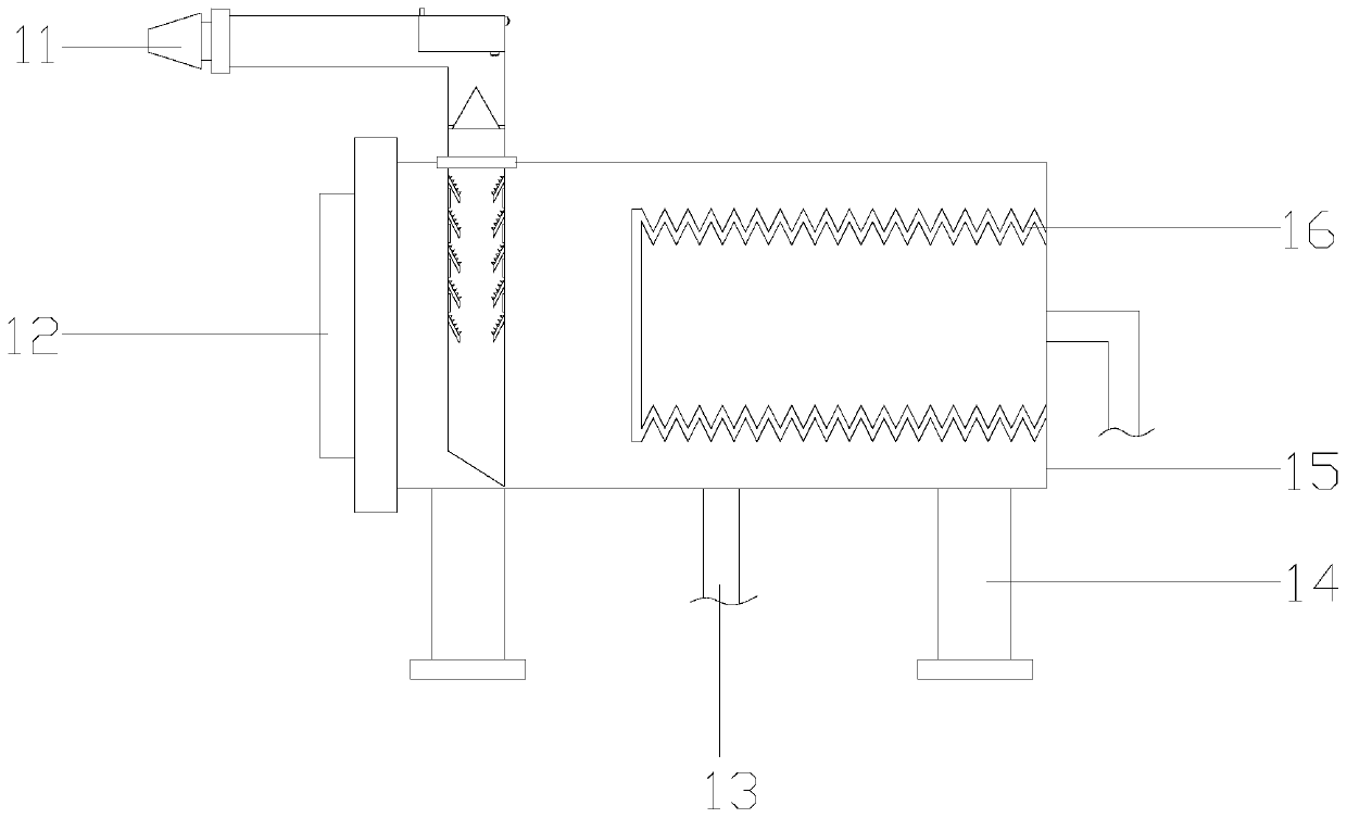
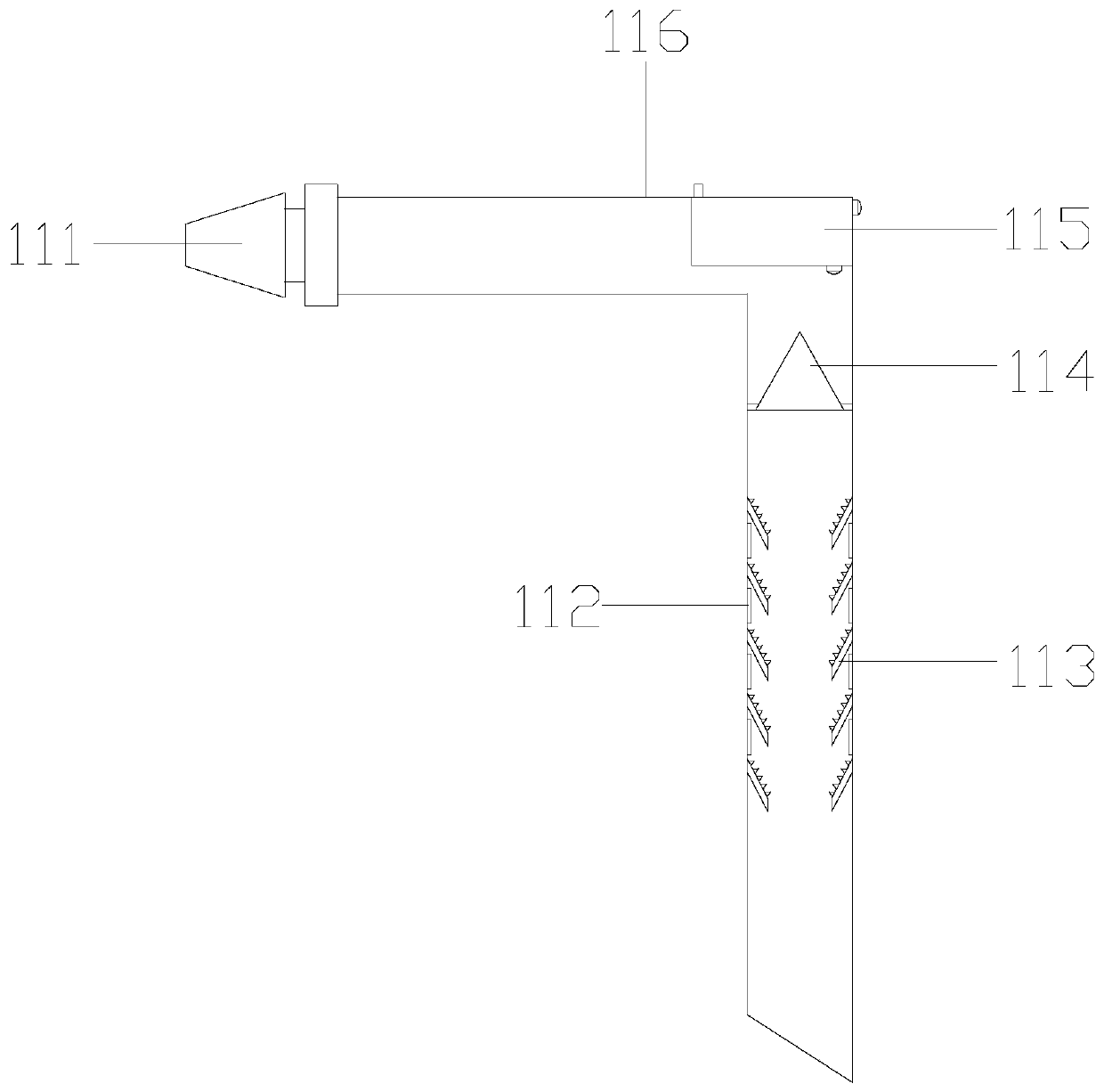
[0029] see Figure 1-Figure 2, the present invention provides an oil-immersed power transformer based on negative pressure anti-overflow filling, its structure includes an oil conservator 1, a low-voltage terminal 2, a transformer main body 3, an oil discharge pipe 4, a transformer hook 5, and a high-voltage terminal 6, The transformer main body 3 is horizontally fixed above the support by bolts, and the transformer hook 5 is provided with two bottom surfaces welded together with the left and right ends of the upper surface of the transformer main body 3 respectively. The upper surface is threaded, the oil conservator 1 is located above the transformer main body 3 and the bottom is connected through the left end of the upper surface of the transformer main body 3, and the high-voltage terminal 6 is located behind the low-voltage terminal 2 and parallel to the low-voltage terminal 2. The left end of the oil discharge pipe 4 is sealed and connected to the bottom of the right sid...


PUM


Abstract

The invention discloses an oil-Immersed power transformer based on negative pressure anti-spill filling. The structure of the oil-Immersed power transformer comprises an oil pillow, a low-voltage connection terminal, a transformer body, an oil drain pipe, a transformer hook and a high-voltage connection terminal. The oil-immersed power transformer is provided with the anti-filling structure, negative pressure is formed in the oil tank body through the negative pressure drive structure when replenishing the transformer oil of the transformer oil pillow so that workers only need to insert one end of the oil guide pipe into the barrel transformer oil bucket and the other end is connected with the oil pipeline connector for filling, thereby avoiding the need for the workers to carry a large amount of transformer oil to climb onto the transformer bracket and improving the safety of filling; meanwhile, the air bubbles in the transformer oil can be directly discharged, the quality of the transformer oil can be improved and the insulation performance of the transformer oil can be ensured.

Description

technical field [0001] The invention relates to the field of transformers, in particular to an oil-immersed power transformer based on negative pressure overflow-proof filling. Background technique [0002] With the continuous development of the national grid, transformers have become an indispensable equipment in circuit transmission, and transformers with strong performance and easy maintenance are required in the power supply and distribution systems of industrial and mining enterprises and civil buildings, so oil-immersed power transformers have become the majority The user's choice, and the transformer is usually installed on a support more than 2.5 meters above the ground for safety and to reduce surrounding noise, but the current technical considerations are not perfect, and it has the following disadvantages: [0003] After the transformer has been used for a long time, in order to ensure the stability of the transformer, it is necessary to change the oil of the tran...

Claims


Application Information

Patent Timeline
Patent Type & Authority Applications(China)
IPC IPC(8): H01F27/14
CPCH01F27/14
Inventor 苏清芬林忠江阿兰庄玉琼
Owner 国网黑龙江省电力有限公司大兴安岭供电公司
Learn More