Low-delay video splicing method, device and system
A video splicing and low-latency technology, applied in the field of video splicing, can solve problems such as large surgical movements, inconvenient operation for doctors, and patient injuries
- Summary
- Abstract
- Description
- Claims
- Application Information
AI Technical Summary
Problems solved by technology
Method used
Image
Examples
Embodiment 1
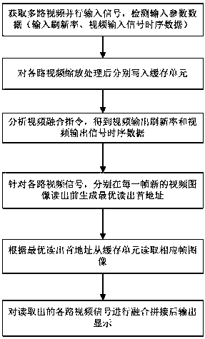
[0064] This embodiment is a low-latency video splicing method, refer to figure 1 As shown, the methods include:
[0065] Obtain parallel input signals of multiple channels of video, and detect the input refresh rate of each video signal and video input signal timing data; video input signal timing data includes the total number of lines of a frame of video input signal and the effective number of lines of a video input signal ;
[0066] Scaling each channel of video signals according to a preset ratio, and writing the scaled each channel of video signals into the buffer unit respectively;
[0067] Obtain the video fusion instruction information, the video fusion instruction information includes the output refresh rate of each video after fusion and video output signal timing data; the video output signal timing data includes the total number of lines of a frame of video output signal , the effective number of lines of a frame of video signal after scaling is ;
[...
Embodiment 2
[0092] This embodiment is a low-latency video splicing device, including:
[0093] The video input signal acquisition and detection module is used to obtain parallel input signals of multiple channels of video, and detect the input refresh rate of each video input signal and video input signal timing data;
[0094] The video scaling and buffer writing module is used to scale each video signal according to a preset ratio, and write the scaled video signals into the buffer unit respectively;
[0095] The video fusion command analysis module is used to obtain video fusion command information, and the video fusion command information includes the output refresh rate of each video after fusion and video output signal timing data;
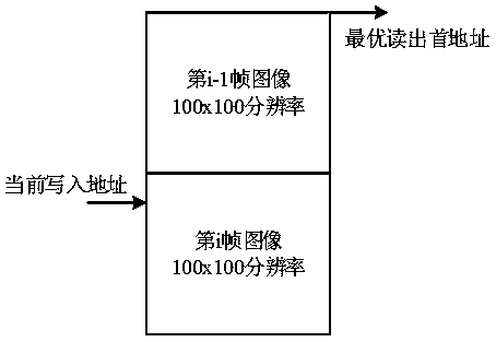
[0096] The optimal read first address generation module is used to write the address based on the current cache and the input refresh rate , video input signal timing data, output refresh rate And video output signal timing data to generate the c...
Embodiment 3
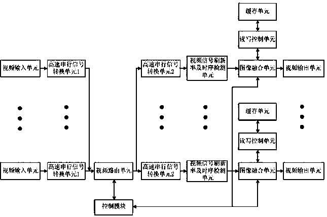
[0103] This embodiment is a low-latency video splicing system, refer to image 3 As shown, the system includes a video input module, a video routing module, a video signal processing module and a control module;
[0104] The video input module includes a plurality of video input channels, each video input channel respectively receives video input signals and converts the video signals into high-speed serial signals; each video input channel is respectively provided with a video input unit and a high-speed serial signal conversion unit 1 in turn, The video input unit is used to receive a video input signal to be spliced together, and convert the received signal into a parallel signal; the high-speed serial signal conversion unit 1 converts the parallel signal output by the video input unit into a unified high-speed serial signal;
[0105] The video signal received by the video input unit has different signal formats depending on the interface type. The video input unit is an ...
PUM
 Abstract
Description
Claims
Application Information
 - R&D
- Intellectual Property
- Life Sciences
- Materials
- Tech Scout
- Unparalleled Data Quality
- Higher Quality Content
- 60% Fewer Hallucinations
Browse by: Latest US Patents, China's latest patents, Technical Efficacy Thesaurus, Application Domain, Technology Topic, Popular Technical Reports.
© 2025 PatSnap. All rights reserved.Legal|Privacy policy|Modern Slavery Act Transparency Statement|Sitemap|About US| Contact US: help@patsnap.com


