Thermostatic test tube rack for reproductive department

A test tube rack and constant temperature technology, which is applied in the direction of test tube support/clamp, water bath/sand bath/air bath, etc., can solve the problems such as the inability to effectively use the heating area of ​​the constant temperature water bath, the inability to adjust the distance between the test tube and the incubator, and the limited number of test tubes. , to achieve the effect of novel design, high reliability and strong practicability

Inactive Publication Date: 2019-07-12
赵红岩
View PDF6 Cites 6 Cited by
  • Summary
  • Abstract
  • Description
  • Claims
  • Application Information

AI Technical Summary

Problems solved by technology

The current method is to clamp the test tube with a separate test tube clamp standing outside the incubator for heating, or put it into the incubator with a test tube rack commonly used in the room, and place the test tube to be heated in the test tube rack for heating, but Since one test tube clamp can only hold one test tube, the heating area of ​​the constant temperature water bath cannot be effectively used, and the method of placing the test tube rack in the constant temperature tank will affect the heating effect because part of the test tubes are blocked by the test tube clamps.
[0004] Chinese patent (notification number: CN205340882U) discloses a test tube rack used on a constant temperature water bath, including a beam, and a U-shaped card slot is arranged on each side of the beam. The U-shaped card slot is inverted, and the beam is connected to two The inner side walls of the U-shaped card slots are connected, and the outer walls of the two U-shaped card slots are provided with screw fixing devices. Although this device can realize the placement of multiple test tube racks, in actual operation, on the one hand, it is impossible to adjust the distance between the test tubes and the racks. The distance between the incubators, on the other hand, only one beam is set, the number of test tubes placed is still very limited, and the practicability is not strong

Method used


Image

  • Thermostatic test tube rack for reproductive department
  • Thermostatic test tube rack for reproductive department
  • Thermostatic test tube rack for reproductive department

Examples


Embodiment 1

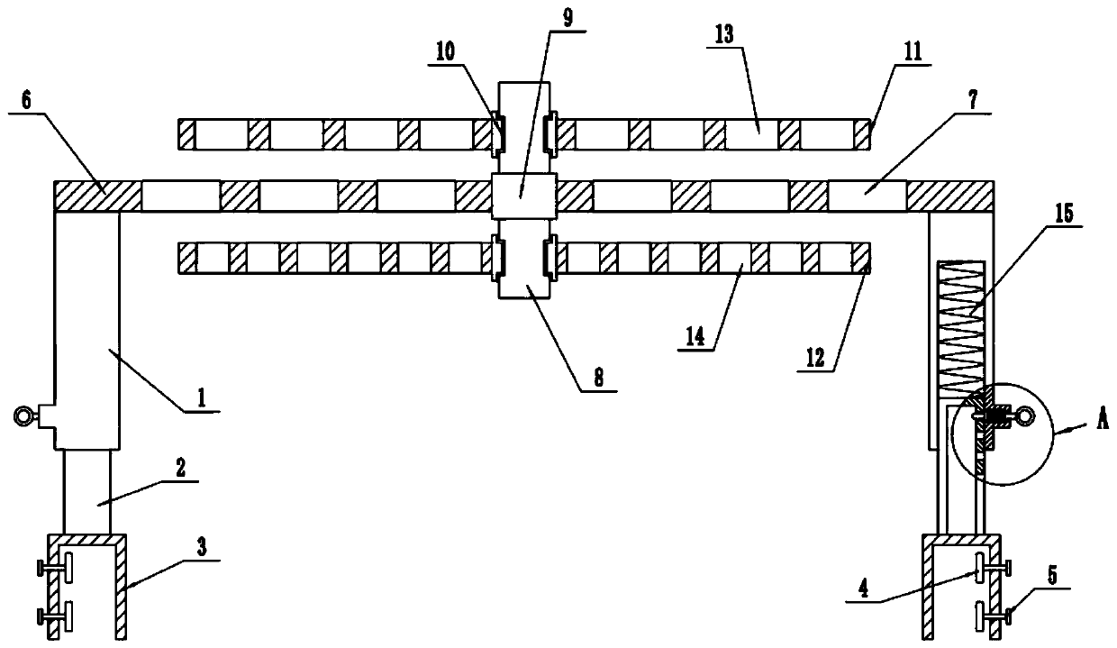
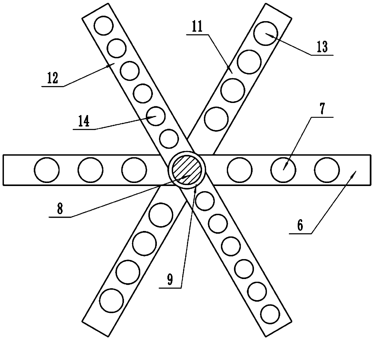
[0025] refer to figure 1 and image 3 , in an embodiment of the present invention, a thermostatic test tube rack for reproductive department, comprising a fixing clip 3, a fixing screw 5 is installed in the middle of the fixing clip 3, and a clamping block 4 is connected to the inner side of the fixing screw 5, and the fixing screw 5 is rotated so that The clamping block 4 can move back and forth along the middle part of the fixing clip 3, so that the fixing clip 3 is fixed to the tank wall of the constant temperature water tank. The upper end of the fixing clip 3 is equipped with an inner telescopic frame 2, and the top end of the inner telescopic frame 2 passes through a telescopic spring 15 The outer telescopic frame 1 is connected, so that during the up and down movement of the outer telescopic frame 1, the inner telescopic frame 2 can give the outer telescopic frame 1 a supporting and buffering effect, thereby avoiding shaking support during the adjustment process. The to...

Embodiment 2

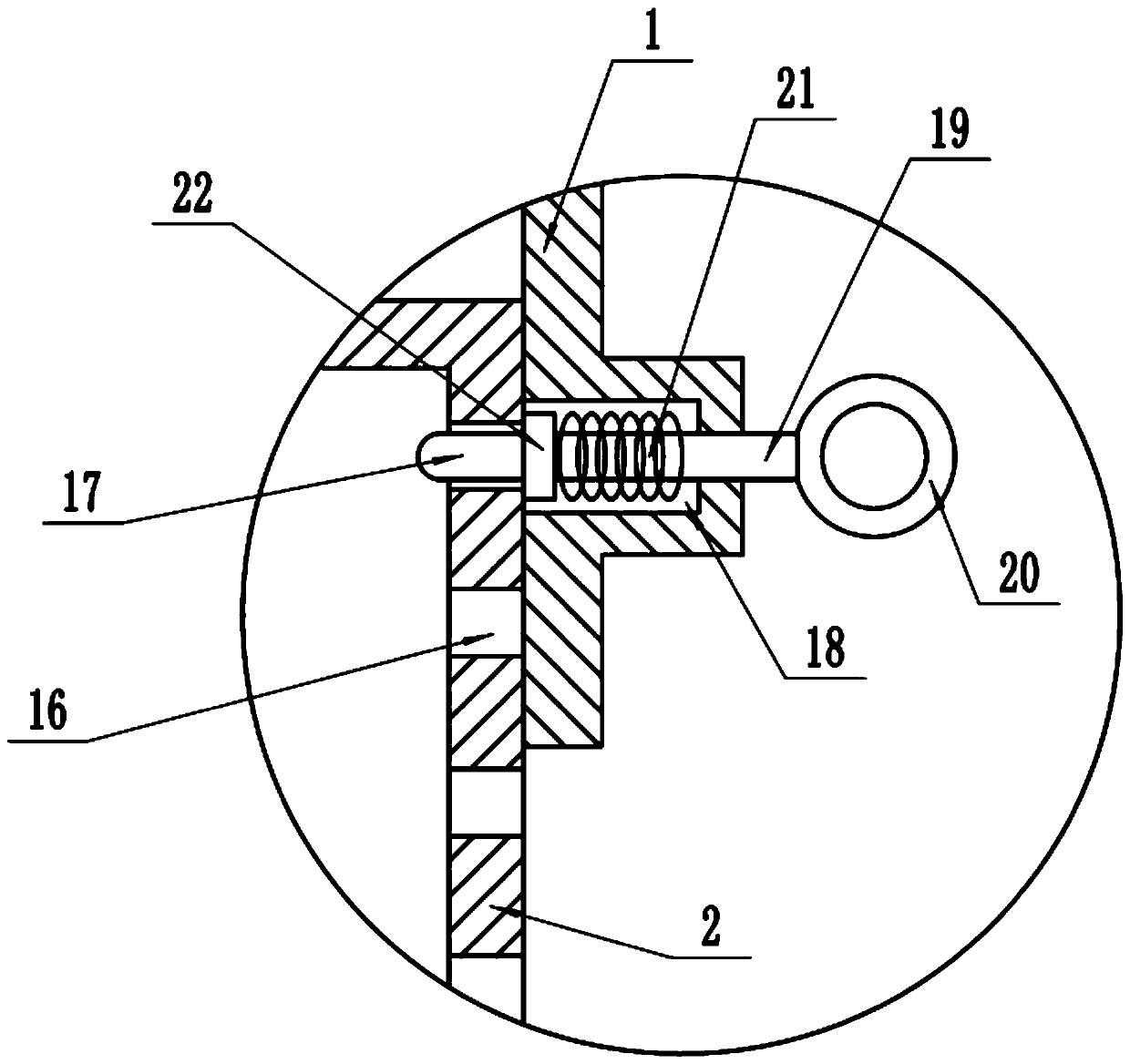
[0028] In another embodiment of the present invention, the difference between this embodiment and the above-mentioned embodiment is that the outer side of the telescopic rod 19 passes through the middle of the telescopic cavity 18 and is connected with a telescopic ring 20. By setting the telescopic ring 20, it is convenient for the staff to The adjustment of the position of the telescopic rod 19 is convenient and reliable.

[0029] In the present invention, when in use, the fixing clip is clamped inside the incubator, and then the fixing screw is rotated so that the clamping block fixes the incubator, and then the telescopic ring is pulled outward, so that the telescopic ring drives the telescopic rod to move outward, thereby making the The telescopic head is separated from the telescopic hole, and then through the up and down adjustment of the telescopic spring, the position between the outer telescopic frame and the inner telescopic frame is continuously adjusted, and then t...


PUM


Abstract

The invention discloses a thermostatic test tube rack for the reproductive department, and belongs to the technical field of medical apparatus and instruments for the reproductive department. The testtube rack comprises fixing clamps, wherein inner telescopic frames are mounted at the upper ends of the fixing clamps, the top ends of the inner telescopic frames are connected with outer telescopicframes through telescopic springs, telescopic cavities are formed in outer sides of the bottom ends of the outer telescopic frames, telescopic rods are mounted inside the telescopic cavities, telescopic blocks are connected to the inner sides of the telescopic rods, telescopic heads are connected to the inner sides of the telescopic blocks and inserted into telescopic holes formed in the outer walls of the inner telescopic frames, the top ends of the outer telescopic frames are connected with lifting rods, the middle of the lifting rods is connected with a fixing column through a fixing sleeve, sliding sleeves are connected with the middles of the upper and lower ends of the fixing column respectively, an upper test tube rod is connected with the middle of the sliding sleeve on the upper side, and a lower test tube rod is connected with the middle of the sliding sleeve on the lower side. Adjustment of the upper and lower positions between a thermostatic box and test tubes is realized,constant temperature requirements of the test tubes with different heights are met, constant temperature heating of a plurality of test tubes is also realized, and interference between the test tubesis avoided, so that the heating effect is further improved.

Description

technical field [0001] The invention relates to the technical field of reproductive medical equipment, in particular to a constant temperature test tube rack for reproductive. Background technique [0002] Since ancient times, the continuation of organisms, including human beings, has been carried out through the combination of the sexes, and the conception and development of sperm eggs in the mother's body. With the development of modern medicine, in order to treat infertility, genetic diseases, implement eugenics and family planning, improve human quality, can change the process of natural reproduction of organisms, without sexual intercourse, and artificially operate methods to give birth to the next generation, This new technology of reproductive medicine developed in the 1970s is called reproductive medicine. [0003] The constant temperature water bath is a heating device that is often used in indoor experiments. When heating the solution in the test tube, since there...

Claims


Application Information

Patent Timeline
Patent Type & Authority Applications(China)
IPC IPC(8): B01L9/06B01L7/02
CPCB01L7/02B01L9/06
Inventor 赵红岩
Owner 赵红岩
Why Eureka
Try Eureka