Method for determining length of plugging section and turning distance of new fracture during temporary plugging fracturing at tip of shale fracture

A crack tip and section length technology, which is applied in the fields of earthwork drilling, sealing/isolation, and special data processing applications, etc., can solve the problems of small construction difficulty, reduce variance, and limit the expansion distance of new cracks, and achieve high efficiency. The effect of mining and reducing drilling costs

Active Publication Date: 2019-07-12
NORTHEASTERN UNIV
View PDF3 Cites 3 Cited by
  • Summary
  • Abstract
  • Description
  • Claims
  • Application Information

AI Technical Summary

Problems solved by technology

[0004] The traditional refracturing methods mostly use 1) secondary fracturing without temporary plugging agent and 2) secondary fracturing with temporary plugging agent plugging the hole. The increase in production is not significant; in the latter case, it is more difficult to completely seal the hole because the subsequent fracturing fluid is easy to break through the original hole roar
In addition, the diversion distance of new fractures caused by the inconspicuous geostress diversion around the wellbore is limited
Both the fluid pressure in the fracture and the formation pressure have a significant ef

Method used

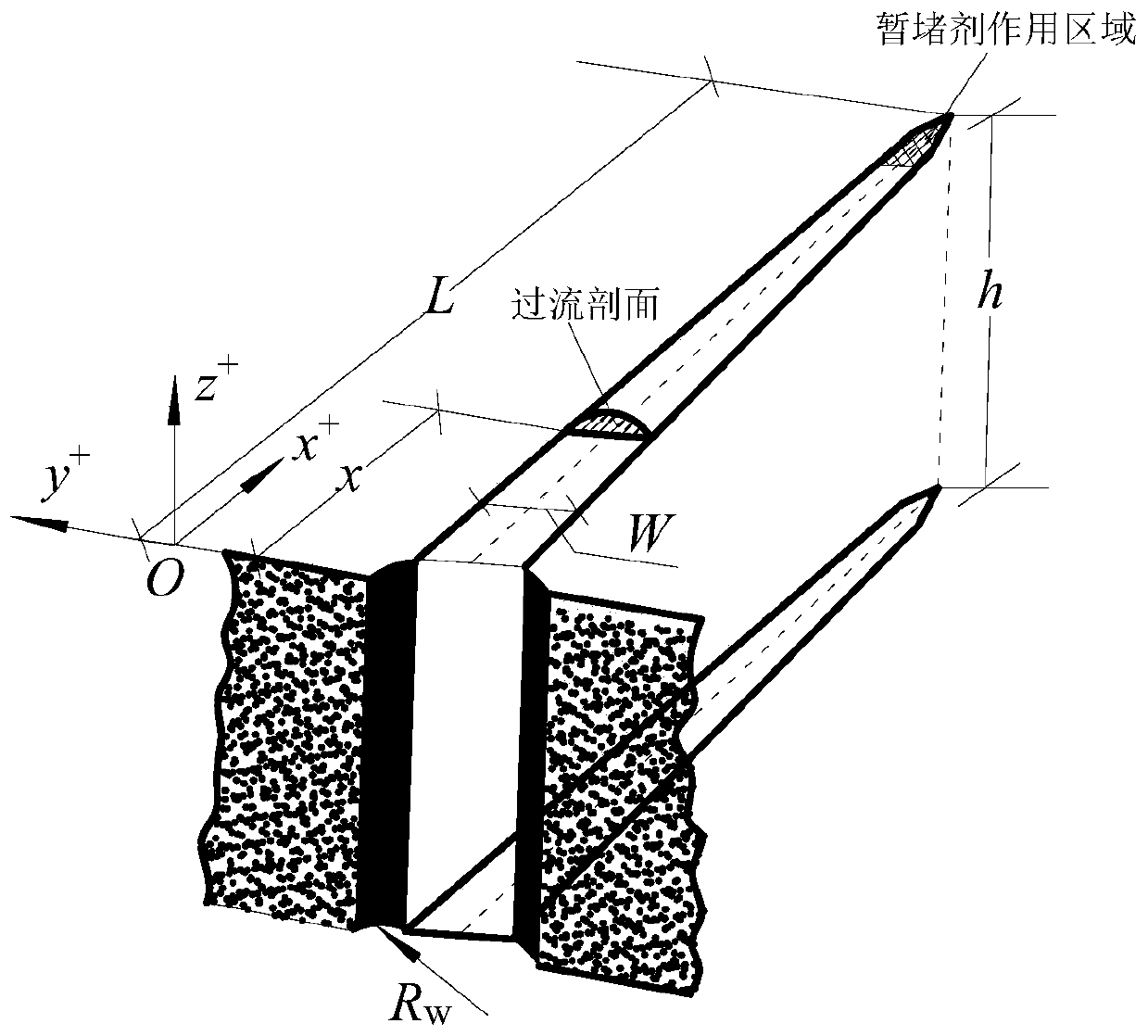
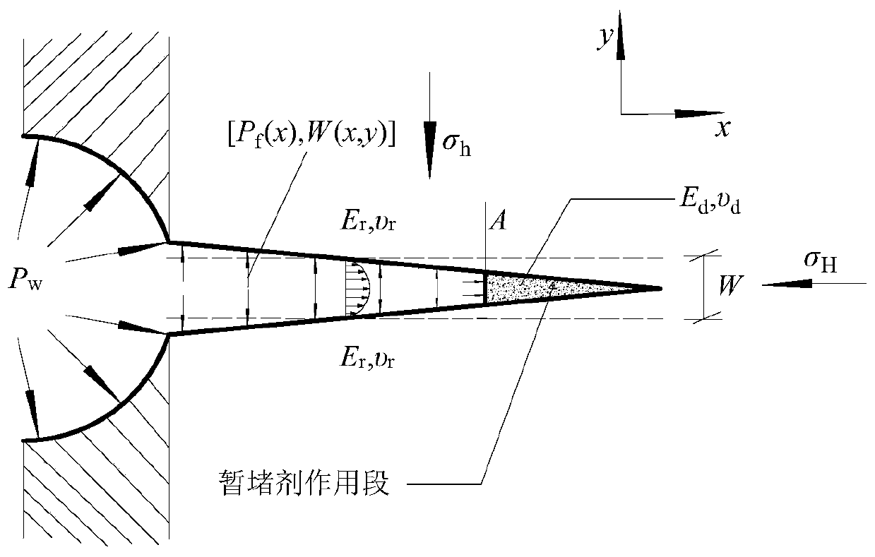
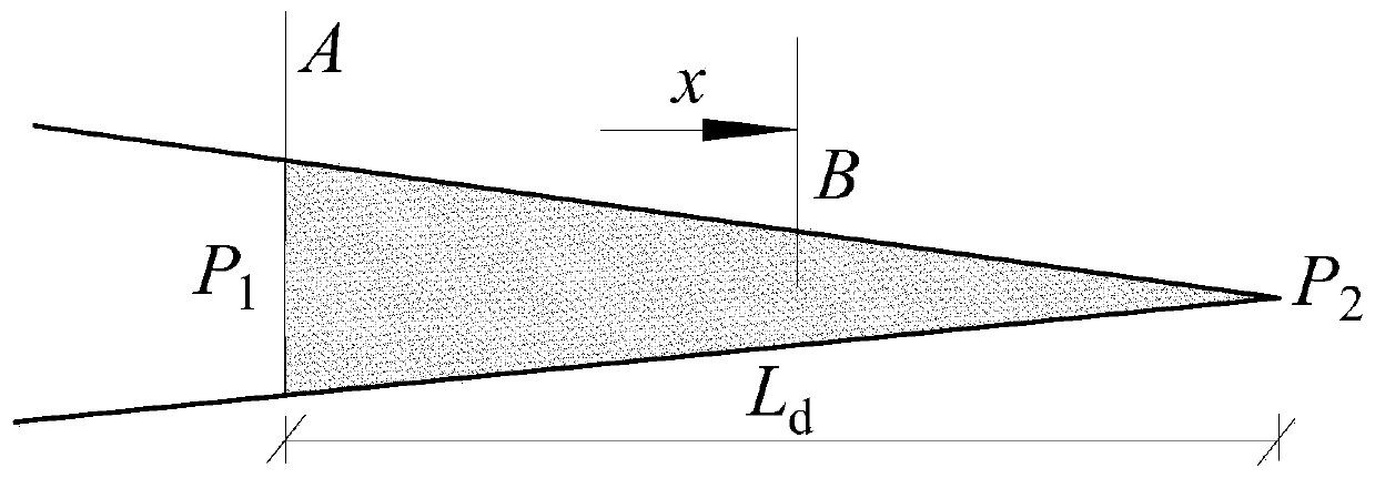

Image

  • Method for determining length of plugging section and turning distance of new fracture during temporary plugging fracturing at tip of shale fracture
  • Method for determining length of plugging section and turning distance of new fracture during temporary plugging fracturing at tip of shale fracture
  • Method for determining length of plugging section and turning distance of new fracture during temporary plugging fracturing at tip of shale fracture

Examples


Example Embodiment

[0049] The technical solutions of the present invention will be clearly and completely described below with reference to the embodiments of the present invention and the accompanying drawings. Obviously, the described embodiments are only a part of the embodiments of the present invention, rather than all the embodiments. Based on the embodiments of the present invention, all other embodiments obtained by those of ordinary skill in the art without creative efforts shall fall within the protection scope of the present invention.

[0050] In order to make the above objects, features and advantages of the present invention more clearly understood, the present invention will be described in further detail below with reference to the accompanying drawings and specific embodiments.

[0051] In the specific implementation process, the present invention provides a method for determining the length of the plugging section and the turning distance of a new fracture during temporary plugg...


PUM


Abstract

The invention relates to a new process design method of an unconventional oil and gas reservoir repeated fracturing technology, in particular to a method for determining the length of a plugging section and the turning distance of a new fracture during temporary plugging fracturing at the tip of a shale fracture. The method comprises the steps that a temporary plugging agent is injected into the tip of the pressure fracture, and after fracturing fluid enters a main fracture, the pressure of the fracturing fluid in the main fracture forms a stress shadowing effect around the fracturing fluid; the stress state around the original main fracture is affected by the stress shadowing effect; the induced stress is superposed with the original ground stress, and the original ground stress state changes; the tip of the fracture is completely plugged, and new fracture with different direction from the original fracture is generated at the end of the plugging section; and further, at the free surface of the temporary plugging agent, the temporary plugged fractured new fracture extends perpendicular to the original fracture direction until the induced stress difference is equal to the horizontal ground stress difference, and the turning distance of the new fracture is calibrated at the position by giving the actual horizontal ground stress difference. Therefore, the potential resources of shale gas on the two sides of the main fracture surface are reasonably exploited.

Description

technical field [0001] The invention relates to a new process design method for the repeated fracturing technology of oil and gas reservoirs, in particular to a method for determining the length of the plugging section and the turning distance of new fractures during temporary plugging and fracturing at the tip of shale fractures, and belongs to a new type of repeated fracturing The technology mainly focuses on the secondary efficient exploitation of oil and gas resources in unconventional reservoirs such as shale and tight oil layers. Background technique [0002] my country's shale gas resources are very rich, and it is expected to become a new oil and gas growth point. At present, hydraulic fracturing and horizontal drilling technology are the main stimulation methods used in shale gas exploitation at home and abroad. However, the permeability and porosity of shale gas reservoirs are extremely low, and volume fracturing of the reservoir is required to make the fracturing...

Claims


Application Information

Patent Timeline
IPC IPC(8): E21B43/26E21B33/13G06F17/50
CPCE21B43/26E21B33/13G06F30/20
Inventor 朱万成于永军李连崇张秀凤魏晨慧牛雷雷李相熙
Owner NORTHEASTERN UNIV
Why Eureka
Try Eureka