In-bottle blending mixing mechanism

A technology for adjusting parts and adjusting valves, which is applied in the field of in-bottle blending and mixing mechanisms, can solve the problems that the proportioning ratio cannot meet the requirements of customers, cannot meet the output requirements of mixed liquid, and the production efficiency is low, and achieves an easy-to-understand experience. , Ingenious design, stable assembly effect

Pending Publication Date: 2019-07-12
YIBIN PLASTIC PACKAGING MATERIALS CO LTD SICHUAN
View PDF0 Cites 0 Cited by
  • Summary
  • Abstract
  • Description
  • Claims
  • Application Information

AI Technical Summary

Problems solved by technology

With the traditional preparation mechanism, on the one hand, manual operation is not only time-consuming and material-consuming, each operation can only be prepared for one concentration ratio, which cannot meet the output requirements of the existing industrial production for the mixed solution to a large extent, and the operation is cumbersome ; On the other hand, the prepared ratio depends to a large extent on the proficiency and experience of the operator, resulting in the ratio of the components in the final mixed liquid that cannot meet the customer's requirements
[0004] In view of the above problems, there are many types of blending equipment on the market, but most of them are only suitable for the preparation of a single mixing ratio. During the blending process, the canning is complicated, the operation is cumbersome and the production efficiency is low.

Method used


Image

  • In-bottle blending mixing mechanism
  • In-bottle blending mixing mechanism
  • In-bottle blending mixing mechanism

Examples


Embodiment 1

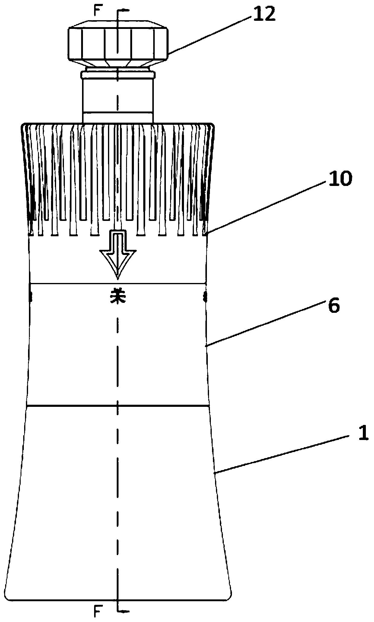
[0043] Such as figure 1 As shown, in this embodiment, an in-bottle blending and mixing mechanism is specifically provided, including an upper container 4 and a lower container 1, both of which are in a cylindrical structure, that is, the upper container 4 has two ends Open cylindrical structure, the lower container 1 is a cylindrical structure with one end open, to simplify the assembly difficulty between the upper container 4 and the lower container 1, the upper container 4 and the lower container 1 are the basic carriers for realizing the technical solution, Different fillers are filled in the upper container 4 and the lower container 1 respectively: A filler and B filler.

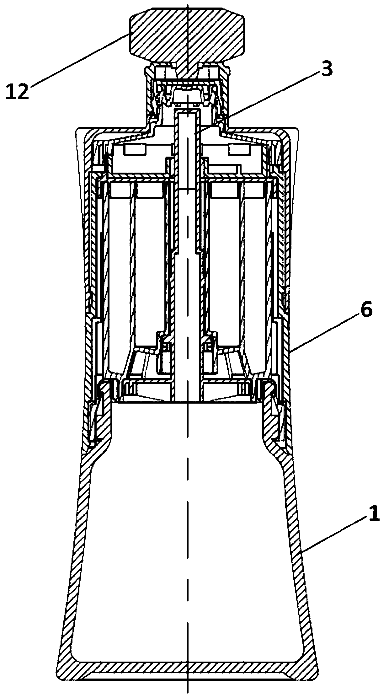
[0044] Such as figure 2 As shown, one end of the upper container 4 is sealed with an interlocking assembly, and the other end is hermetically assembled with the lower container 1, and under the cooperation of the interlocking assembly, the upper container 4 and the lower container 1, they together form...

Embodiment 2

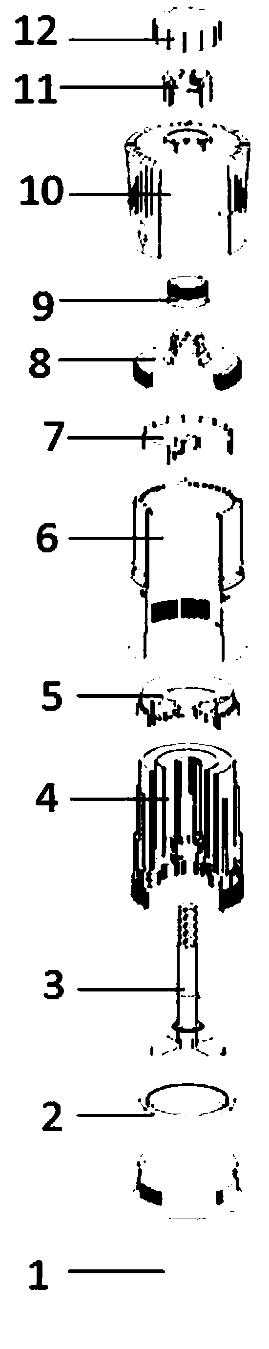
[0050] Such as Figure 4 As shown, in order to realize the stable assembly between the hooking part 7 and the hooking inner plug 5 and to better operate the normal operation of the hooking part 7, it also includes a rotating part 10 and a bottle mouth 8 installed inside it, and the rotating part 10 It is also made into a cylindrical structure, and the end of the rotating member 10 can be directly sleeved on the end of the upper container 4 (for example: the most conventional buckle and ring groove can be used), and the rotating member 10 rotates During the movement, the hooking part 7 is linked with the bottle mouth 8 to make a rotary motion. During the movement of the hooking part 7, the inner ring cavity and the outer ring cavity can be communicated with the bottle mouth 8 respectively or simultaneously, so as to continuously switch the inner ring cavity and the outer ring cavity. In the open or closed state of the outer ring cavity, at the same time, the hook adjustment par...

Embodiment 3

[0055] Such as Figure 5 , Figure 15 As shown, on the basis of the above-mentioned embodiment 1 and embodiment 2, in order to further improve the assembly stability and assembly difficulty between the rotating member 10, the interlocking assembly, the upper container 4 and the lower container 1, it also includes the The connecting piece 6 outside the above-mentioned container 4, one end of the connecting piece 6 is sleeved in the rotating piece 10 and the end is provided with a connecting piece anti-reset boss 21 and two connecting piece shrapnel 20, and the other end part is socketed with the lower container 1; the end of the bottle mouth 8 facing the connecting piece 6 is provided with a bottle mouth stopper, under the action of the bottle mouth stopper and the elastic piece 20 of the connecting piece, the rotation direction of the rotating member 10 can be limited , in order to play the role of anti-counterfeiting, under the action of the anti-reset boss 21 of the connect...


PUM


Abstract

The invention discloses an in-bottle blending mixing mechanism, and belongs to the technical field of liquid mixing. The in-bottle blending mixing mechanism comprises an upper container and a lower container, wherein one end of the upper container is hermetically equipped with a blending assembly, and the other end is hermetically equipped with the lower container; a central shaft cavity, an innerring cavity and an outer ring cavity are sequentially arranged in the upper container along the same axis and communicate with the inner cavity of the lower container; the central shaft cavity is movably provided with a blending valve core internally, and the blending valve core moves up and down in the central shaft cavity to connect or disconnect the inner ring cavity and the outer ring cavity,the inner cavity and the inner cavity of the lower container, or the outer ring cavity and the inner cavity of the lower container; the blending assembly comprises a blending inner plug and a blending piece, wherein the blending piece rotates relative to the blending inner plug to enable the inner ring cavity and the outer ring cavity to form outlets separately or simultaneously, the blending valve core is linked to move up and down, so that fillers in the inner ring cavity and the outer ring cavity sequentially fall into the lower container, the purpose of blending and preparing the two fillers in the blending process is achieved, the blending efficiency is improved and the operation difficulty is lowered.

Description

technical field [0001] The invention belongs to the technical field of liquid mixing, and in particular relates to an in-bottle blending and mixing mechanism. Background technique [0002] In the process of industrial production, some products need to be blended and finally formed. Take the brewing process of liquor as an example. Liquor fermentation is a wine product made by using cooked grains as raw materials, fermented by microorganisms, and then processed. After high-temperature cooking and gelatinization, koji powder rich in microorganisms can be added after cooling to a lower temperature. After a period of closed fermentation, it can be converted into alcohol and other aroma substances, and steamed to produce white wine. The blending of the steamed wine and various wines is called blending; the main function of the blending wine is to make the proportion of various trace components in the wine appropriate, so as to meet the standard requirements of this kind of liquo...

Claims


Application Information

Patent Timeline
Patent Type & Authority Applications(China)
IPC IPC(8): F16K11/02B01F15/04B01F15/00
CPCF16K11/02B01F35/00B01F2035/351B01F35/80
Inventor 胡昌红郭伟东杨多兵王传龙周立权阳培翔杨吉红刁厚昌凌生愉柳洋杨齐高灵强
Owner YIBIN PLASTIC PACKAGING MATERIALS CO LTD SICHUAN
Why Eureka
Try Eureka