Saturation control method of seafloor accuracy landing of tethered cabled underwater robot based on sliding mode technology
A technology of underwater robot and control method, applied in the direction of adaptive control, general control system, control/adjustment system, etc., can solve problems such as economic loss, underwater structure collision or even accident, time-consuming and labor-intensive, etc., to improve accuracy, improve The effect of fixed-point landing accuracy
- Summary
- Abstract
- Description
- Claims
- Application Information
AI Technical Summary
Problems solved by technology
Method used
Image
Examples
specific Embodiment approach 1
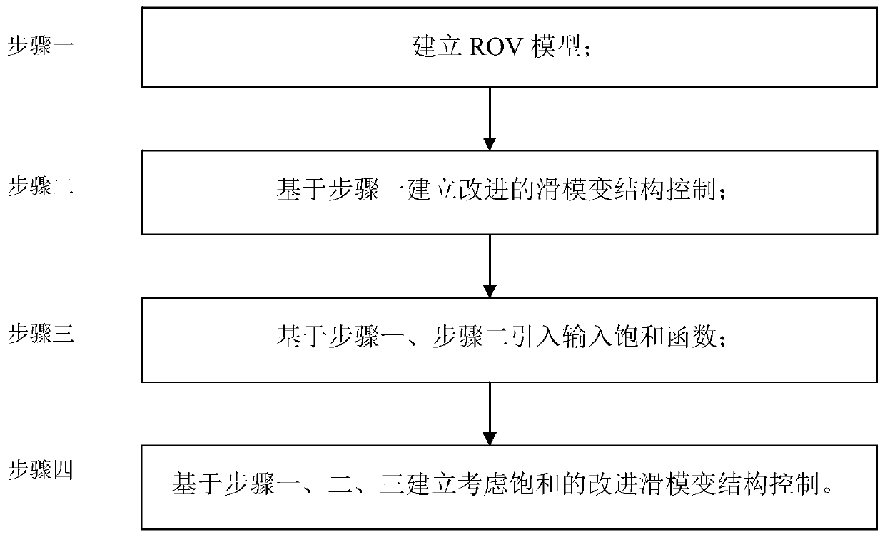
[0040] Embodiment 1: The specific process of the saturation control method for the fixed-point landing of the cabled underwater robot based on the sliding mode technology in this embodiment is as follows:
[0041] (1) Definition of the relevant coordinate system for ROV research: inertial coordinate system (E-ξηζ): the origin E can be selected at a certain point on the sea surface, the Eξ axis and the Eη axis are placed in the horizontal plane and are perpendicular to each other, and the Eξ axis is positive pointing to the north direction. Eζ is perpendicular to the Eξη plane, pointing to the center of the earth;
[0042] Motion coordinate system G-xyz: the origin G is taken at the center of gravity of the ROV, and the x-axis, y-axis and z-axis are the intersection lines of the water plane, transverse section and mid-longitudinal section passing through the origin respectively;
[0043] (2) ROV modeling technology: Fossen-based six-degree-of-freedom nonlinear ROV model [1] ([...
specific Embodiment approach 2
[0068] Embodiment 2, the difference between this embodiment and Embodiment 1 is that: the expression of the conversion matrix J for converting the inertial coordinate system to the motion coordinate system in the step 1 is:
[0069]
[0070] in,
[0071]
[0072]
[0073] In the formula, s' is the sine function sin; c' is the cosine function cos; t' is the tangent function tan; is the displacement transformation matrix, and T' is the attitude transformation matrix.
[0074] Other steps and parameters are the same as in the first embodiment.
specific Embodiment approach 3
[0075] Embodiment 3, the difference between this embodiment and Embodiment 1 or 2 is that: in step 2, an improved sliding mode variable structure control is established based on step 1; the specific process is:
[0076] Sliding mode variable structure control has the advantages of fast response and insensitivity to parameter changes and disturbances, and has been favored by the majority of scientific researchers in recent years. However, due to the existence of chattering problems, sliding mode variable structure control has been continuously improved. Until today, the chattering problem is still a research hotspot of sliding mode variable structure control. Reference [2] ([2]Tanakitkorn K, Wilson PA, Turnock S R, et al. Sliding mode heading control of an over actuated, hover-capable autonomous underwater vehicle with experimental verification [J]. Journal of Field Robotics, 2017.) An idea of approximating the sign function using the hyperbolic tangent function is proposed ...
PUM
 Abstract
Description
Claims
Application Information
 - R&D
- Intellectual Property
- Life Sciences
- Materials
- Tech Scout
- Unparalleled Data Quality
- Higher Quality Content
- 60% Fewer Hallucinations
Browse by: Latest US Patents, China's latest patents, Technical Efficacy Thesaurus, Application Domain, Technology Topic, Popular Technical Reports.
© 2025 PatSnap. All rights reserved.Legal|Privacy policy|Modern Slavery Act Transparency Statement|Sitemap|About US| Contact US: help@patsnap.com


