

Energy storage component and electric energy storage device
A technology of energy storage components and energy storage parts, which is applied in the direction of electrical components, circuits, capacitors, etc., can solve problems such as potential safety hazards, and achieve the effects of improving safety, facilitating operation and judgment, and increasing precision and accuracy
- Summary
- Abstract
- Description
- Claims
- Application Information
AI Technical Summary
Problems solved by technology
Method used
Image

Examples
Embodiment 1
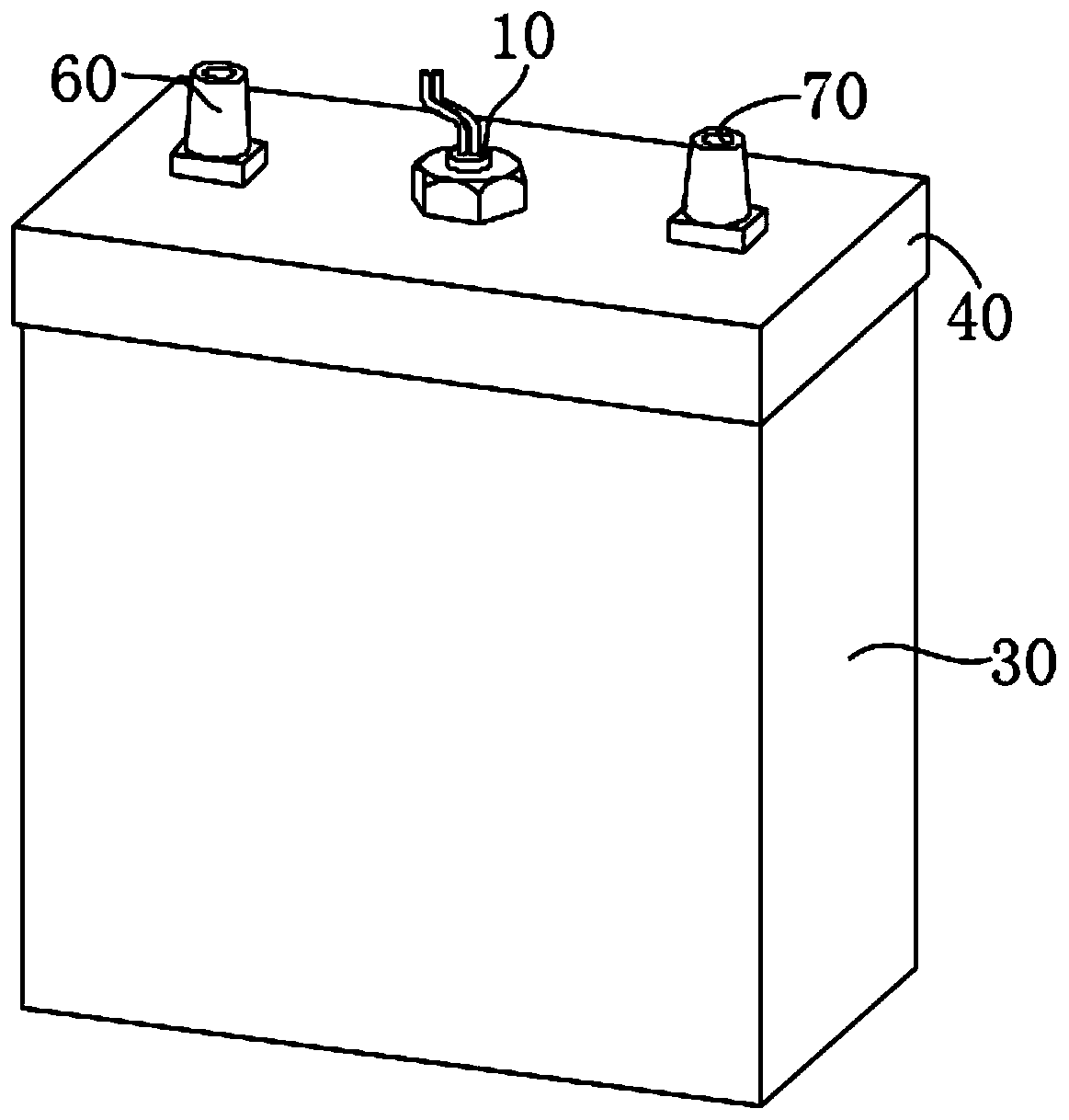
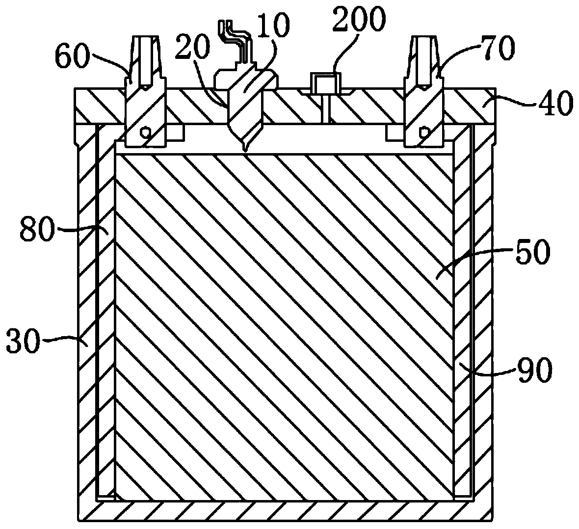
[0049] Such as figure 1 and figure 2 As shown, the energy storage element provided in this embodiment includes an energy storage element and a sensor device 10; It is used to detect the internal pressure and internal temperature of the energy storage parts.
[0050] Specifically, the sensing device 10 can extend into the energy storage element, so that the detection end of the sensing device 10 is located inside the energy storage element, and then detect the internal pressure and temperature inside the energy storage element.
[0051] The energy storage element can directly install the sensor device 10 inside the energy storage component, that is, the sensor device 10 can directly contact the internal pressure and temperature of the energy storage component, so that the sensor device 10 can directly detect the internal temperature of the energy storage component. Pressure and internal temperature, without intermediate transmission process, and then reduce the difference betw...
Embodiment 2
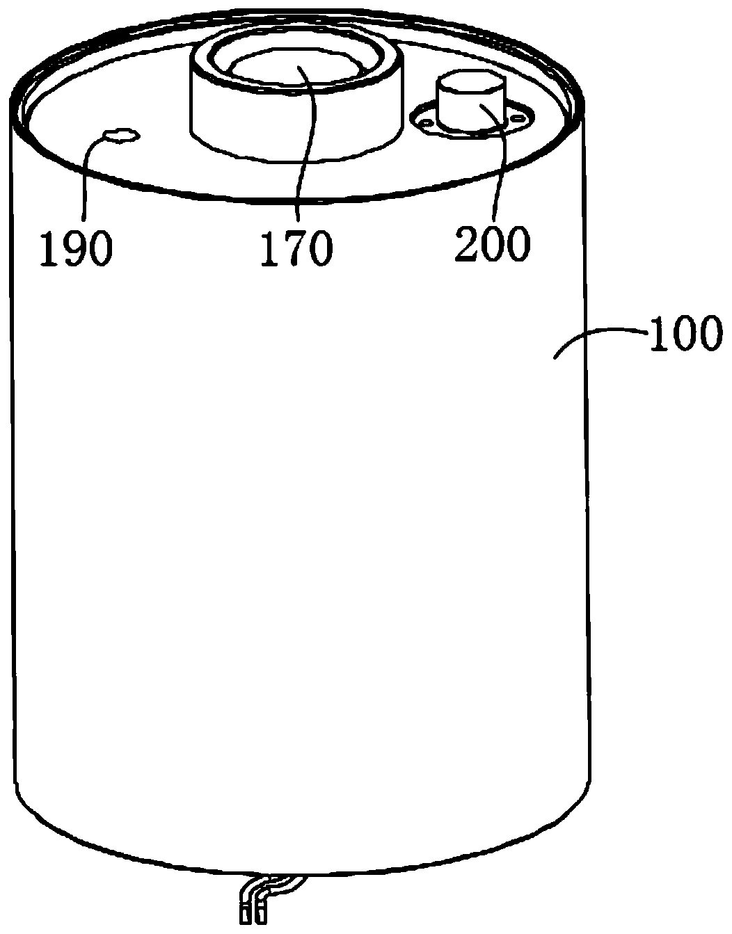
[0064] Such as image 3 and Figure 4 As shown, this embodiment also provides an energy storage element, which is different from the energy storage element in Embodiment 1 in that the energy storage element as described below includes a second shell 100, a top cover, and a central shaft 130; the second shell 100 encloses a second cavity with a second opening, the top cover is sealed at the second opening, the central shaft 130 is located in the second cavity, and is socketed with the top cover; the installation hole 20 is along the axial direction of the central shaft 130 The central shaft 130 runs through, and the central shaft 130 has a plurality of microholes 1301 communicating with the installation hole 20 and the second cavity.
[0065] Specifically, the second housing 100 is surrounded by a cylinder, and the interior of the cylinder is hollow to form a cylindrical second cavity, and the top and bottom surfaces of the cylinder are respectively opened to form a second ope...
Embodiment 3
[0084] This embodiment also provides an electric energy storage device, comprising a plurality of the above-mentioned energy storage elements, and the plurality of energy storage elements are arranged in series or in parallel.
[0085]Specifically, a plurality of energy storage elements can be serially connected in series to form a large-capacity electric energy storage device, which is convenient for use by equipment with a large demand for electric energy. Moreover, each energy storage element has a sensing device 10, thereby facilitating detection of the internal pressure and internal temperature of each energy storage element.
[0086] What needs to be added is that it is not limited to the arrangement of "multiple energy storage elements arranged in series", but also the arrangement method of "multiple energy storage elements arranged in parallel", as long as multiple energy storage elements can be connected It is sufficient to form a large-capacity electric energy storag...
PUM
 Abstract
Description
Claims
Application Information