
Switching power supply protection circuit and switching power supply protection strategy

A switching power supply and protection circuit technology, applied in emergency protection circuit devices, electrical components, output power conversion devices, etc., can solve the problems of high device temperature and power supply cannot be cut off.

Active Publication Date: 2019-07-12
SUZHOU WEICHUANG ELECTRICAL EQUIP TECH
View PDF12 Cites 5 Cited by
  • Summary
  • Abstract
  • Description
  • Claims
  • Application Information

AI Technical Summary

Problems solved by technology

[0008] In order to solve the technical problems that the power supply cannot be cut off and the temperature of the device is too high when the switching power supply is short-circuited, the embodiment of the present invention provides a switching power supply protection circuit and a switching power supply protection strategy

Method used


Image

  • Switching power supply protection circuit and switching power supply protection strategy
  • Switching power supply protection circuit and switching power supply protection strategy
  • Switching power supply protection circuit and switching power supply protection strategy

Examples


Embodiment 1

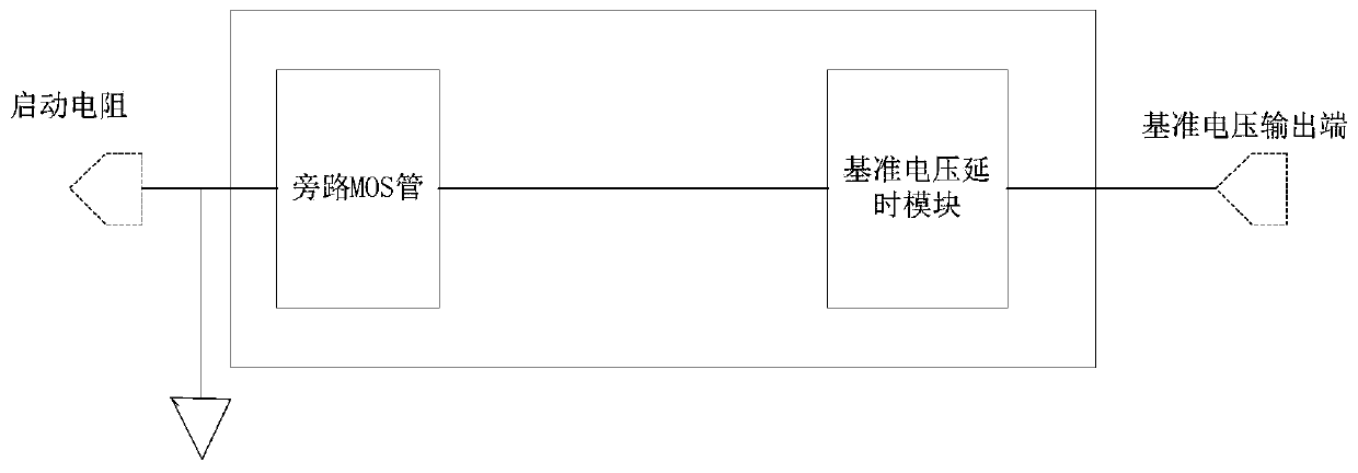
[0061] figure 1 A schematic diagram of a switching power supply protection circuit provided by an embodiment of the present invention, refer to figure 1 , the switching power supply protection circuit includes:

[0062] Reference voltage delay module and bypass MOS tube;

[0063] The input terminal of the reference voltage delay module is connected with the reference voltage output terminal (VREF) of the switching power supply control chip for time delay;

[0064] The control terminal of the bypass MOS transistor is connected to the output terminal of the reference voltage delay module, and the control voltage is provided through the charge and discharge module;

[0065] The bypass MOS transistors are also respectively connected to the startup resistor and the ground, and the bypass MOS transistors are closed to connect the startup resistors to the ground.

[0066] Specifically, in the embodiment of this application, the function of the delay of the reference voltage delay ...

Embodiment 2

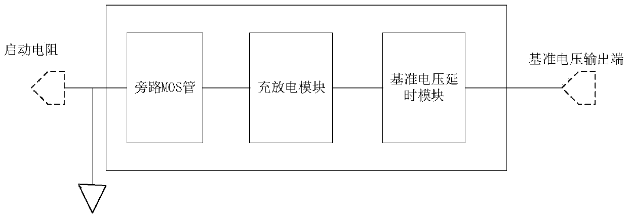
[0069] figure 2 A schematic diagram of a switching power supply protection circuit provided by an embodiment of the present invention, refer to figure 2 , the switching power supply protection circuit includes:

[0070] Reference voltage delay module, charge and discharge module and bypass MOS tube;

[0071] The input terminal of the reference voltage delay module is connected with the reference voltage output terminal (VREF) of the switching power supply control chip for time delay;

[0072] The input terminal of the charging and discharging module is connected to the output terminal of the reference voltage delay module, and the charging is performed through the reference voltage delay module;

[0073] The control terminal of the bypass MOS tube is connected to the output terminal of the charging and discharging module, and the control voltage is provided through the charging and discharging module;

[0074] The bypass MOS transistors are also respectively connected to ...

Embodiment 3

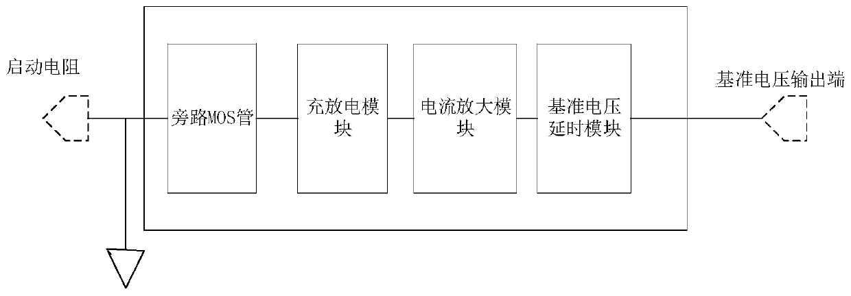
[0078] image 3 A schematic diagram of a switching power supply protection circuit provided by an embodiment of the present invention, refer to image 3 , the switching power supply protection circuit includes:

[0079] Reference voltage delay module, charge and discharge module, current amplification module and bypass MOS tube;

[0080] The input terminal of the reference voltage delay module is connected with the reference voltage output terminal (VREF) of the switching power supply control chip for time delay;

[0081] The input terminal of the current amplification module is connected to the reference voltage delay module, and the output terminal is connected to the input terminal of the charging and discharging module, which is used to increase the current output by the reference voltage delay module, that is, to increase the charging and discharging module. The charging current of the discharging module, thereby accelerating the charging speed of the charging and disch...


PUM


Abstract

The embodiment of the present invention provides a switching power supply protection circuit and a switching power supply protection strategy. The switching power supply protection circuit comprises abypass MOS transistor that grounds a starting resistor of a switching power supply in a switched-on state, in order to ensure that the switching power supply can establish output before the bypass MOS transistor is switched on, the switching power supply protection circuit is also provided with a reference voltage delay module for delay. After the switching power supply establishes the output andthe bypass MOS transistor is switched on, the starting resistor is grounded, power is not supplied to a power supply voltage input end of a switching power supply control chip, and at that time, thepower supply voltage input terminal of the switching power supply control chip is only powered by a switching power supply transformer. When the output of the switching power supply is short-circuited, the switching power supply transformer immediately stop the power supply to the power supply voltage input terminal of the switching power supply control chip, in this way, the power supply of the switching power supply control chip is quickly cut off, and a problem that the cut of the power supply of the switching power supply control chip is delayed to cause a too long operation time in an abnormal short circuit state and excessive device loss is avoided.

Description

technical field [0001] The embodiments of the present invention relate to the technical field of circuit protection, and in particular to a switching power supply protection circuit and a switching power supply protection strategy. Background technique [0002] With the rapid development of science and technology, all kinds of electronic products are increasingly entering people's lives. Electronic products have changed our lives again and again. People's basic necessities of life are increasingly inseparable from electronic products. We are all familiar with these Familiar electronic products such as mobile phones, TVs, computers, washing machines, air conditioners, and automobiles are inseparable from the support of auxiliary power supplies, and switching power supplies occupy the vast majority of auxiliary power supplies. If there is a problem with the switching power supply, the entire product will be damaged. The function of the system will be paralyzed, and the impact ...

Claims


Application Information

Patent Timeline
IPC IPC(8): H02H7/12H02M1/36
CPCH02H7/12H02M1/36
Inventor 李丽艳周义军骆鹏
Owner SUZHOU WEICHUANG ELECTRICAL EQUIP TECH
Learn More