A predictive current-mode control method for a gan-based active-clamp flyback converter

A technology of flyback converter and current prediction, which is applied in the direction of converting DC power input to DC power output, control/regulation systems, instruments, etc. It can solve the problems of switching loss and conduction loss that cannot be compromised, so as to reduce the difficulty, The effect of reducing loss and improving efficiency

Active Publication Date: 2021-09-07
SOUTHEAST UNIV
View PDF12 Cites 0 Cited by
  • Summary
  • Abstract
  • Description
  • Claims
  • Application Information

AI Technical Summary

Problems solved by technology

[0005] The purpose of the present invention is to address the shortcomings of the above-mentioned background technology and provide a predictive current mode control method for a GaN-based active clamp flyback converter. The working condition can be directly obtained by looking up the working condition of the circuit after checking the table The valley current and dead time corresponding to the lowest loss point can quickly reach the best working state, reduce loss, improve efficiency, and solve the problem that the existing active clamp flyback converter control strategy cannot compromise switching loss and conduction. The technical problem that the total loss must be minimized when the pass loss is exactly exactly ZVS

Method used


Image

  • A predictive current-mode control method for a gan-based active-clamp flyback converter
  • A predictive current-mode control method for a gan-based active-clamp flyback converter
  • A predictive current-mode control method for a gan-based active-clamp flyback converter

Examples


Embodiment Construction

[0026] The technical solution of the invention will be described in detail below in conjunction with the accompanying drawings.

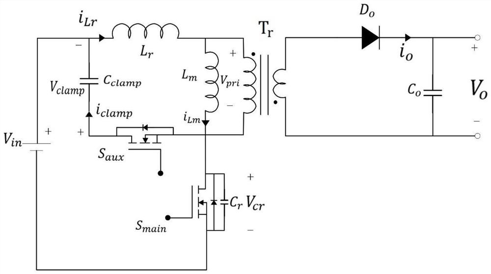
[0027] The topology of an active clamp flyback converter used in this example is as follows figure 1 shown, including: input DC source V in , Transformer T r , Resonant inductance L r , Exciting inductance L m , main power tube S main , Secondary power tube S aux , clamp capacitor C clamp , Diode D 0 , output filter capacitor C o , where the resonant inductance L r and magnetizing inductance L m can be regarded as a transformer T r a part of. Resonant inductance L r One end of the clamp capacitor C clamp One pole and the input DC source V in The positive terminal is connected, the resonant inductance L r The other end of the magnetizing inductance L m one end of the transformer T r One end of the primary winding is connected to the transformer T r The other end of the primary winding, the exciting inductance L m The other end of t...


PUM


Abstract

The invention discloses a predictive current mode control method of a GaN-based active clamp flyback converter, which belongs to the technical field of power generation, power transformation or power distribution. The present invention deduces the relationship between the converter loss and the valley current under a certain working condition by means of theoretical calculation, obtains the valley current and the corresponding dead time that minimize the loss, and stores them in the LUT unit in the form of a five-element array Middle; the control method can determine the valley current and dead zone time of the next cycle through the LUT unit through the sampling signal, thereby controlling the conduction time of the auxiliary switch and the dead zone time from when the auxiliary switch is turned off to when the main switch is turned on, avoiding The freewheeling loss and the loss caused by the reverse charging of the parasitic capacitance of the main switch can enter the high-efficiency working state after a period of adjustment, reducing the loss and improving the efficiency; the GaN-based power tube makes the dynamic performance of the converter more efficient. Well, for higher operating frequency, lower parasitic parameters further reduce loss and improve efficiency.

Description

technical field [0001] The invention discloses a predictive current mode control method for a GaN-based active clamp flyback converter, in particular to a predictive hysteresis current mode control method for a GaN-based active clamp flyback converter, which belongs to power generation and power transformation Or the technical field of power distribution. Background technique [0002] In today's power supply field, MOS tubes mostly use Si-based materials and GaN-based materials. GaN has the advantages of wide band gap, high critical breakdown electric field, high saturation electron drift velocity, and high electron mobility, which makes GaN-based materials MOS Compared with the MOS tube of Si-based material, the tube has the advantages of small on-resistance and fast switching speed, which greatly reduces the on-state loss and switching loss of the device, thereby improving the efficiency and operating frequency of the converter. In addition, GaN-based materials have highe...

Claims


Application Information

Patent Timeline
Patent Type & Authority Patents(China)
IPC IPC(8): H02M3/335H02M1/38H02M1/08
CPCH02M1/083H02M1/38H02M3/33569H02M1/0058H02M1/385Y02B70/10
Inventor 钱钦松冶前增许胜有杨兰兰孙伟锋时龙兴
Owner SOUTHEAST UNIV
Why Eureka
Try Eureka