Power factor correction circuit and air conditioner

A power factor correction and circuit technology, applied in emergency protection circuit devices, output power conversion devices, instruments, etc., can solve problems such as poor practicability, and achieve the effect of boosting and power factor improvement

Pending Publication Date: 2019-07-12
GD MIDEA AIR-CONDITIONING EQUIP CO LTD
View PDF0 Cites 8 Cited by
  • Summary
  • Abstract
  • Description
  • Claims
  • Application Information

AI Technical Summary

Problems solved by technology

[0004] like figure 1 As shown, the existing protection scheme can only realize the detection when the upper and lower Q1 and Q3 are abnormal, or the upper and lower Q2 and Q4 are abnormal. circuit, it is very difficult to have a direct connection between the upper and lower bridge arms, so the probability of faults corresponding to this protection scheme is very low, and the practicability is relatively poor

Method used


Image

  • Power factor correction circuit and air conditioner
  • Power factor correction circuit and air conditioner
  • Power factor correction circuit and air conditioner

Examples


Embodiment 1

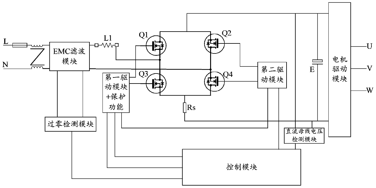
[0055] Such as figure 2 As shown, the power factor correction circuit according to an embodiment of the present invention is suitable for an air conditioner, and includes: a power factor correction module 10 for receiving a power supply signal, the power factor correction module 10 includes a switching tube, and the switching tube is configured In order to control the power supply signal to supply power to the load; the driving module is connected to the driving input end of the switching tube, and is used to output the switching signal to the switching tube; the control module 30 is connected to the driving module, and is used to control the switching tube The drive module turns on and outputs the switch signal or closes the output of the switch signal; the current transformer 40 is arranged on the input side of the power factor correction module to collect sampling signals; the drive protection module 50 is connected to the current transformer And the control module is conn...

Embodiment 2

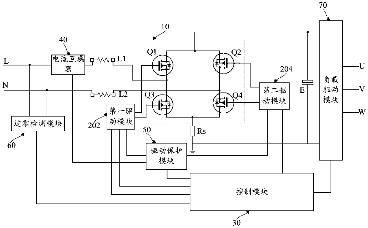
[0059] Such as figure 2 As shown, in the above embodiment, optionally, further include: a sampling resistor Rs, set at the negative output terminal of the power factor correction module 10, and connected to the drive protection module 50, the drive protection module 50 After detecting that the voltage drop on the sampling resistor Rs exceeds the second safety threshold, the control module 30 outputs the protection signal.

[0060] In this embodiment, a current transformer 40 is connected in series on the AC side of the power factor correction module 10 to be responsible for detecting the current on the AC side, and then the voltage signal output by the sensor is used as the input signal for driving the protection module 50, combined with The sampling resistor Rs connected in series at the negative output terminal of the power factor correction module 10, the voltage detected by the sampling resistor Rs is also input into the drive protection module 50, when any of the two inp...

Embodiment 3

[0067] Such as figure 2 As shown, in any one of the above embodiments, optionally, the power factor correction module 10 is formed by a first switching tube Q1, a second switching tube Q2, a third switching tube Q3 and a fourth switching tube Q4, The first switching tube Q1 and the second switching tube Q2 are arranged on the upper part of the power factor correction module 10, the third switching tube Q3 and the fourth switching tube Q4 are arranged on the lower part of the power factor correction module 10, the first switching tube Q1 and the third The switch tube Q3 is arranged on the left part of the power factor correction module 10, the second switch tube Q2 and the fourth switch tube Q4 are arranged on the right part of the power factor correction module 10, the first switch tube Q1, the second switch tube Q2, the third switching tube Q3 and the fourth switching tube Q4 both have freewheeling diodes, the drain of the first switching tube Q1 is connected in series with ...


PUM


Abstract

The invention provides a power factor correction circuit and an air conditioner. The power factor correction circuit comprises a power factor correction module, a driving module, a control module, a current transformer and a driving protection module; the power factor correction module receives a power supply signal and comprises a switch tube, and the switch tube is configured to control the power supply signal to supply power to a load; the driving module is connected to the driving input end of the power factor correction module, and used to output a switch signal to the switch tube; the control module is connected to the driving module, and controls the driving module to start or stop output of the switch signal; the current transformer is arranged in the input side of the power factorcorrection module to collect a sampling signal; and the driving protection module is connected with the current transformer and the control module, and outputs a protection signal to the control module. Thus, whether a rectifier is abnormal can be detected more directly, and when there is abnormity, a corresponding abnormal part can be determined in different conditions.

Description

technical field [0001] The invention relates to the technical field of air conditioners, in particular to a power factor correction circuit and an air conditioner. Background technique [0002] In the related art, the power factor correction circuit (Power Factor Correction, PFC circuit) adopts high-power MOS switching technology as the main power device to replace the IGBT device, and uses the characteristic of MOS low conduction resistance to replace the characteristic of constant conduction voltage drop of IGBT to achieve The power consumption under low and medium power is reduced to reduce the power consumption of the air conditioner. [0003] Four switching tubes are used to form a power factor correction module, and two half-bridge driver chips are used to drive. One of the driver chips has a protection function, combined with a sampling resistor for over-current detection. If a large current is detected, it will be triggered to turn off the four switches. Drive outpu...

Claims


Application Information

Patent Timeline
Patent Type & Authority Applications(China)
IPC IPC(8): H02M1/42H02H3/08H02H7/125H02H7/12G01R15/20G01R19/165G01R19/175G01R31/02
CPCH02M1/4208H02H3/08H02H7/125H02H7/12G01R19/16571G01R19/16576G01R19/175G01R15/20G01R31/50Y02B70/10
Inventor 鲍殿生
Owner GD MIDEA AIR-CONDITIONING EQUIP CO LTD
Why Eureka
Try Eureka