Human eye tracking three-dimensional display device with high viewpoint density

A stereoscopic display device and human eye tracking technology, applied in stereoscopic systems, image communications, electrical components, etc., can solve problems such as low parallax continuity and reduced image distribution rate

Active Publication Date: 2019-07-12
CHENGDU TECH UNIV
View PDF13 Cites 8 Cited by
  • Summary
  • Abstract
  • Description
  • Claims
  • Application Information

AI Technical Summary

Problems solved by technology

However, traditional stereoscopic display is limited by the contradiction between the number of viewpoints, viewpoint density and viewing area range. When the number of viewpoints is fixed, the larger the viewing area range, the fewer the number of viewpoints in the unit area, and the lower the disparity continuity.
If the number of viewpoints is increased to increase the density of viewpoints and the scope of the viewing area, the distribution rate of the image will decrease again.

Method used


Image

  • Human eye tracking three-dimensional display device with high viewpoint density
  • Human eye tracking three-dimensional display device with high viewpoint density
  • Human eye tracking three-dimensional display device with high viewpoint density

Examples


Embodiment

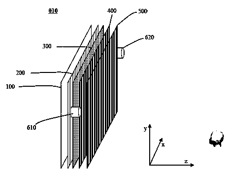
[0022] figure 1 A schematic structural diagram of a high viewpoint density human eye tracking stereoscopic display device 010 provided in this embodiment. In the figure, the x coordinate represents the horizontal direction in space, the y coordinate represents the vertical direction in space, and z represents the direction perpendicular to the x-y plane. Please refer to figure 1 , this embodiment provides a high viewpoint density human eye tracking stereoscopic display device 010, which consists of a 2D display panel 100, a first lenticular lens grating 200, a scattering layer 300, a second lenticular lenticular grating 400, an optical path switch 500, and a first camera 610 and a second camera 620. Wherein the scattering layer 300 is a lens array with a small pitch.

[0023] The human eye tracking stereoscopic display device 010 with high viewpoint density provided by this embodiment will be further described below.

[0024] Please refer to figure 1 , the first camera 61...


PUM


Abstract

The invention provides a human eye tracking three-dimensional display device with high viewpoint density. The display device is composed of a 2D display panel, a first cylindrical lens grating, a scattering layer, a second cylindrical lens grating, an optical path switch, a first camera and a second camera. The first camera and the second camera are used for judging the position of a viewer. The 2D display panel provides a parallax composite image corresponding to a viewer location. The first cylindrical lens grating may narrow a parallax composite image on the 2D display panel to be imaged atthe scattering layer location for reducing pixel pitch. And the smaller pixel spacing is favorable for improving the viewpoint density. And the scattering layer is used for scattering the parallax composite image in the direction of the second cylindrical lens grating. And according to the position of the viewer, the optical path switch projects the parallax composite image to the area where theviewer is located by selecting part of the cylindrical lens on the second cylindrical lens grating. When the human eyes are located in the corresponding watching areas, the corresponding parallax images can be seen, and therefore stereoscopic vision is generated.

Description

technical field [0001] The present invention relates to display technology, more specifically, the present invention relates to stereoscopic display technology. Background technique [0002] 3D display technology is a display technology that can realize the true reproduction of stereoscopic scenes, and it can provide different parallax images for human eyes, so that people can produce stereoscopic vision. Generally, a stereoscopic display device is composed of a light splitting element and a 2D display panel for providing stereoscopic parallax composite images. Through precise coupling, the pixels of the stereoscopic parallax synthesis image can be projected to the specified direction by the light splitting element, thereby forming the viewpoint. However, traditional stereoscopic display is limited by the contradiction between the number of viewpoints, viewpoint density and viewing area range. When the number of viewpoints is fixed, the larger the viewing area range, the sm...

Claims


Application Information

Patent Timeline
Patent Type & Authority Applications(China)
IPC IPC(8): H04N13/383H04N13/239H04N13/305
CPCH04N13/383H04N13/239H04N13/305
Inventor 吕国皎王艳陈宇峰
Owner CHENGDU TECH UNIV
Why Eureka
Try Eureka