Extruding device for thermosetting powder coating production

A technology of thermosetting powder and coating, which is applied in the direction of mixer with rotating stirring device, transportation, packaging, dissolution, etc. It can solve the problems of thermosetting powder coating residue, thermosetting powder coating waste, and affecting the coating process, so as to reduce residue, The effect of avoiding waste, increasing heating speed and heating effect

Active Publication Date: 2019-07-16
ANHUI SUNROAD ENVIRONMENT PROTECTIVE NEW MATERIALS
View PDF6 Cites 5 Cited by
  • Summary
  • Abstract
  • Description
  • Claims
  • Application Information

AI Technical Summary

Problems solved by technology

[0003] However, in actual use, it still has some shortcomings. For example, although it is easier to discharge the material by using the cylinder to push, due to the sticky characteristics of the thermosetting powder coating, there will still be more thermosetting powder coating residue in the mixing chamber. It will not only cause waste of thermosetting powder coatings, but also affect the next coating process

Method used


Image

  • Extruding device for thermosetting powder coating production
  • Extruding device for thermosetting powder coating production
  • Extruding device for thermosetting powder coating production

Examples


Embodiment 1

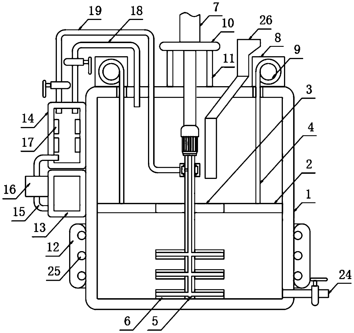
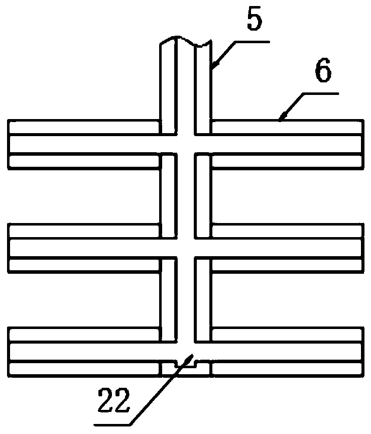
[0024] The present invention provides such as Figure 1-3 A thermosetting powder coating production extrusion device shown includes a housing 1, a scraper 2 is provided inside the housing 1, the edge of the scraper 2 is attached to the housing 1, and the scraper 2 runs through A through hole 3 and a steel wire rope 4 are fixed on the top, a stirring rod 5 is fixed inside the through hole 3, and a stirring plate 6 is sleeved on the outside of the stirring rod 5, and the stirring plate 6 is connected to the through hole 3. Adaptation, the top of the stirring rod 5 is fixed with a cylinder 7, the bottom of the cylinder 7 is fixed with a top plate 10, the bottom of the top plate 10 is fixed with a mounting rod 11, and the mounting rod 11 is fixed on the top of the housing 1 , the top of the housing 1 is fixed with a winding machine 8, the winding machine 8 is provided with a winding wheel 9, and the steel wire rope 4 is fixed on the outside of the winding wheel 9.

[0025] It can...

Embodiment 2

[0027] Further, in the above-mentioned embodiment 1, the outer side of the housing 1 is sleeved with a thermal insulation cover 12 , and the thermal insulation cover 12 is provided with a heating pipe 25 inside.

[0028] Further, in the first embodiment above, the side of the housing 1 is fixed with a gas storage chamber 13 and a heating chamber 14, the gas storage chamber 13 is arranged at the bottom of the heating chamber 14, and the inside of the gas storage chamber 13 is filled with Inert gas, the inert gas is set as nitrogen.

[0029] Further, in the first embodiment above, a connecting pipe 15 is provided on the side of the gas storage chamber 13 and the heating chamber 14 , an air pump 16 is provided on the connecting pipe 15 , and a heating element 17 is provided inside the heating chamber 14 .

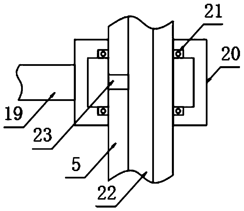
[0030] Further, in the first embodiment above, the top of the heating chamber 14 is provided with a first air intake pipe 18 and a second air intake pipe 19, the second air in...


PUM


Abstract

The invention discloses an extruding device for thermosetting powder coating production. The device comprises a shell; a scraping plate is arranged in the shell, the edge of the scraping plate is attached to the shell, the scraping plate is provided with a through hole in a pass-through manner, and the top of the scraping plate is fixedly provided with steel wire ropes; a stirring rod is fixedly arranged in the inner side of the through hole, stirring plates sleeve the outer side of the stirring rod, and the stirring plates are matched with the through hole; the top of the stirring rod is fixedly provided with an air cylinder, the bottom of the air cylinder is fixedly provided with a top plate, the bottom of the top plate is fixedly provided with installation rods, and the installation rods are fixedly arranged at the top of the shell; and the top of the shell is fixedly provided with winding machines, each winding machine is provided with a winding wheel, and each steel wire rope is fixedly arranged at the outer side of the corresponding winding wheel. According to the device provided by the invention, the scraping plate and the stirring plates cooperate to form a sealed plate shape, so that residues of the thermosetting powder coating is effectively reduced, waste of the thermosetting powder coating can be avoided, and influence on a next coating processing process can be prevented.

Description

technical field [0001] The invention relates to the technical field of thermosetting powder coating processing, in particular to a thermosetting powder coating production extruding device. Background technique [0002] The utility model patent of the patent application publication number CN 207697122 U discloses a thermosetting powder coating production extruding device, including a base, a collection chamber, a protection chamber and a housing, the bottom of the base is equipped with walking wheels, and the top of the base is A casing is installed, and a feeding port is installed at the bottom end of the inside of the casing, and two sets of collection chambers are installed on the top of the feeding port, and a mounting seat is installed inside the collecting chamber, and the bottom of the mounting seat An electric telescopic rod is installed, an extruding plate is installed on the bottom of the electric telescopic rod, and a discharge valve extending out of the housing is...

Claims


Application Information

Patent Timeline
Patent Type & Authority Applications(China)
IPC IPC(8): B01F15/02B01F7/18B01F15/06B01F15/00
CPCB01F27/90B01F35/123B01F35/7546B01F35/91B01F2035/99B01F2101/30
Inventor 黄俊峰
Owner ANHUI SUNROAD ENVIRONMENT PROTECTIVE NEW MATERIALS
Why Eureka
Try Eureka