
Wireless charging device for electric vehicle during driving

A technology for electric vehicles and wireless charging, which is applied in the direction of electric vehicle charging technology, electric vehicles, battery circuit devices, etc., can solve the problems of coupling coefficient change, increase coupling coefficient, and low coupling coefficient, and achieve a large effective magnetic circuit cross-sectional area , short magnetic path length, and high coupling coefficient effects

Pending Publication Date: 2019-07-16
张雁
View PDF3 Cites 1 Cited by
  • Summary
  • Abstract
  • Description
  • Claims
  • Application Information

AI Technical Summary

Problems solved by technology

[0009] The present invention proposes a wireless charging device for electric vehicles that can be driven to solve the problems that the existing wireless charging technology cannot realize high-efficiency wireless charging during the driving process of the vehicle, and the coupling coefficient changes during the moving process and the coupling coefficient is low. The charging of the electric vehicle during the moving process increases the coupling coefficient so that the electric vehicle can continuously gather and receive the magnetic field lines during the driving process to meet the continuous charging process during the driving process of the electric vehicle to improve the efficiency of wireless charging

Method used


Image

  • Wireless charging device for electric vehicle during driving
  • Wireless charging device for electric vehicle during driving
  • Wireless charging device for electric vehicle during driving

Examples


Embodiment Construction

[0039] The following will clearly and completely describe the technical solutions in the embodiments of the present invention with reference to the accompanying drawings in the embodiments of the present invention. Obviously, the described embodiments are only some, not all, embodiments of the present invention. Based on the embodiments of the present invention, all other embodiments obtained by persons of ordinary skill in the art without creative efforts fall within the protection scope of the present invention.

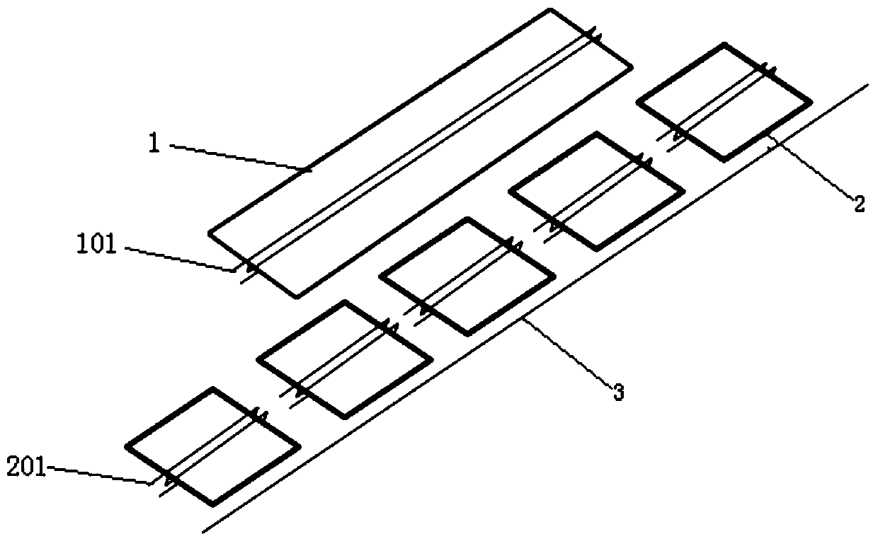
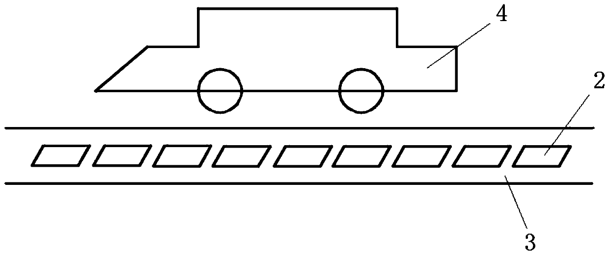
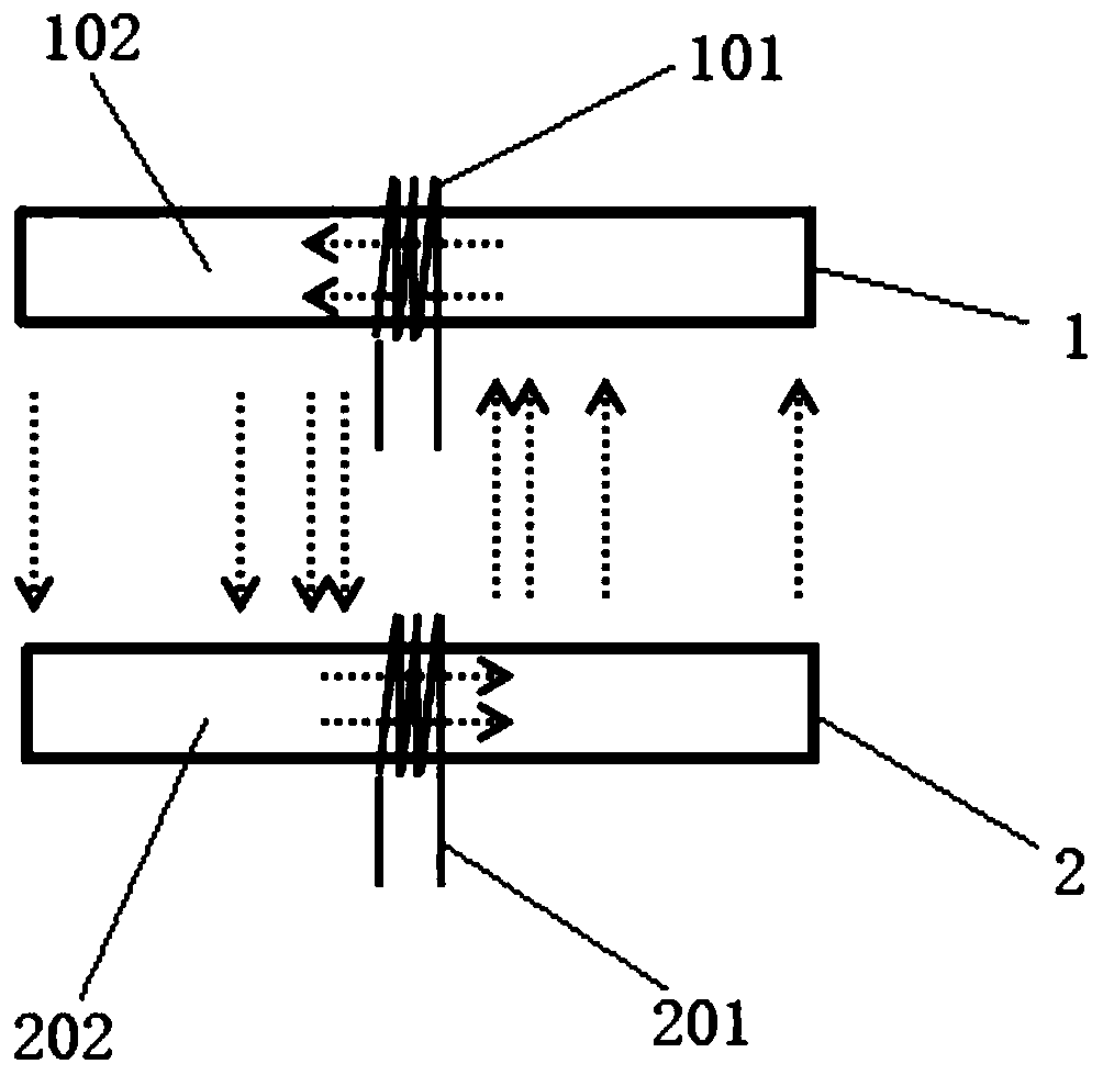
[0040] A traveling wireless charging device for an electric vehicle, combined with Figure 1 to Figure 11 As shown, it includes a transmitting unit 2 and a receiving unit 1 .

[0041] There are several transmitting units 2 arranged in the ground along the roadway 3 , and there is a certain distance between two adjacent transmitting units 2 . The transmitting unit 2 includes a transmitting unit magnetic core 202 and a transmitting coil 201 wound on the transmitting...


PUM


Abstract

The invention provides a wireless charging device for an electric vehicle during driving, and aims to solve the problems that existing wireless charging technologies cannot realize wireless charging of vehicles in the driving process, the coupling coefficient changes in the moving process, and the coupling coefficient is low. The movable wireless charging device includes a plurality of transmitting units, and receiving units are arranged over the transmitting units in a covering mode; and each transmitting unit comprises a transmitting unit magnetic core and a transmitting coil wound on the transmitting unit magnetic core, each receiving unit comprises a receiving unit magnetic core and a receiving coil wound on the receiving unit magnetic core, the winding directions of the transmitter coils and the winding directions of the receiving coils are all parallel to the driving directions of electric vehicles on driving roads, and the magnetic field directions in the transmitting unit magnetic cores and the magnetic field directions in the receiving unit magnetic cores are all parallel to the driving roads and perpendicular to the driving directions of the electric vehicles on the driving roads. According to the wireless charging device for the electric vehicle during driving, energy can be continuously transmitted during driving of the electric vehicles, and high-power wireless charging of the electric vehicles in the driving process can be perfectly realized.

Description

technical field [0001] The invention relates to the technical field of wireless power transmission, in particular to a wireless charging device for electric vehicles during travel. Background technique [0002] With the rapid development of electric vehicles in my country, the biggest bottleneck restricting electric vehicles is the low energy density of the battery and the slow charging speed. At present, electric vehicles must be charged when they are stopped, and the charging time is too long, and the cruising range of electric vehicles is also short, requiring frequent charging. The current charging piles are wired charging piles. Even if there is wireless charging, it cannot realize wireless charging while driving electric vehicles. [0003] Therefore, a device that can support efficient wireless charging for electric vehicles can solve the current problems in electric vehicle charging. It can get rid of the cable shackles of wired charging, and does not require specia...

Claims


Application Information

Patent Timeline
IPC IPC(8): B60L53/12H02J50/10
CPCB60L53/12H02J7/025H02J50/10Y02T10/70Y02T10/7072Y02T90/14
Inventor 张雁
Owner 张雁
Learn More