Unmanned aerial vehicle facilitating shooting

An unmanned aerial vehicle, a convenient technology, applied in the field of unmanned aerial vehicles, can solve the problems of limited shooting angle, affecting the quality of shooting, large space occupied by support feet, etc., so as to increase the shooting angle, and facilitate shooting observation and operation. handy effect

Inactive Publication Date: 2019-07-16
杭州点钢电子商务有限公司
View PDF5 Cites 3 Cited by
  • Summary
  • Abstract
  • Description
  • Claims
  • Application Information

AI Technical Summary

Problems solved by technology

[0002] When it comes to shooting, the traditional UAV usually has a camera outside the lower end. However, when the machine falls to the ground, the lens is easily scratched by the stones blown by the wind. At the same time, in order to buffer the UAV when it falls The impact force of the equipment often takes up a lot of space for the supporting feet at the bottom of the equipment, which limits the shooting angle and easily blocks the light source, affecting the quality of shooting

Method used


Image

  • Unmanned aerial vehicle facilitating shooting
  • Unmanned aerial vehicle facilitating shooting
  • Unmanned aerial vehicle facilitating shooting

Examples


Embodiment Construction

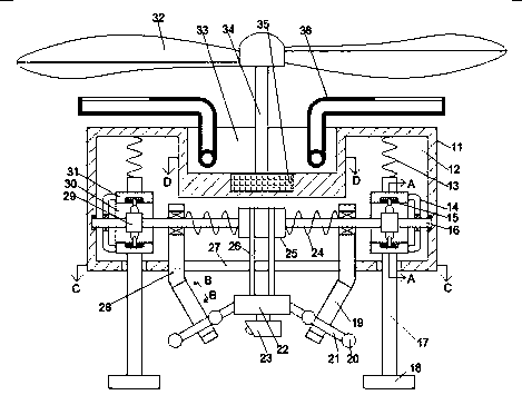
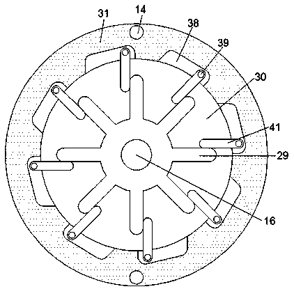
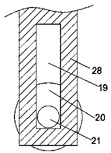
[0019] like Figure 1-Figure 6 As shown, a kind of unmanned aerial vehicle convenient for photographing of the present invention comprises fuselage 11, and described fuselage 11 is provided with transmission chamber 12, and described transmission chamber 12 lower end inner wall communicates and is provided with through hole 27, and described transmission chamber The inner wall of the bottom end of 12 is slidably connected with symmetrical foot rods 17 located at the left and right ends of the through hole 27, and a resistance spring 13 is connected between the upper end of the foot rod 17 and the top inner wall of the transmission chamber 12. The foot rod 17 The lower end is provided with soles 18 that are in contact with the ground, and four center-symmetric track arms 28 are fixedly connected in the through hole 27, and a camera lifting device is slidably connected in the track arms 28, and the transmission chamber 12 is rotationally connected There is a transmission shaft 1...


PUM


Abstract

The invention discloses an unmanned aerial vehiclefacilitating shooting. The unmanned aerial vehicle facilitating shooting includes a vehicle body. A transmission cavity is formed in the vehicle body.A through hole is formed in the inner wall of the lower end of the transmission cavity in a communicating mode. The inner wall of the bottom end of the transmission cavity is slidably connected withfoot rods which are located at the left end and the right end of the through hole and are symmetrical. A resistance spring is connected between the upper end of each foot rod and the inner wall of thetop end of the transmission cavity. A foot sole which is in contact with the ground is arranged in the lower end of each foot rod. The through hole is internally and fixedly connected with four central symmetrical rail arms. A camera lifting device is slidably connected into the rail arms. A transmission shaft extending in the left-right direction is rotatably connected into thetransmission cavity. According to the unmanned aerial vehicle facilitating shooting, in the process of ascending, the camera part is located at the lower end of a branch foot to conveniently shoot and observe and an angle of shooting is enlarged by downward movement of the self-gravity of the unmanned aerial vehicle, while in the process of descending, the camera part can be raised to protect the unmanned aerial vehicle, and automatic working mode differentiation is achieved by using a unidirectional coupling structure in the processes of ascending and descending.

Description

technical field [0001] The invention relates to the technical field of drones, in particular to a drone that is convenient for shooting. Background technique [0002] When it comes to shooting, the traditional UAV usually has a camera outside the lower end. However, when the machine falls to the ground, the lens is easily scratched by the stones blown by the wind. At the same time, in order to buffer the UAV when it falls The impact force of the device often takes up a lot of space for the supporting feet at the lower part of the device, which limits the shooting angle and easily blocks the light source, affecting the quality of shooting. The present invention illustrates a device capable of solving the above-mentioned problems. SUMMARY OF THE INVENTION [0003] The technical problem to be solved by the present invention is to provide a convenient shooting drone, which can solve the above-mentioned problems in the prior art. [0004] The present invention is achieved thr...

Claims


Application Information

Patent Timeline
Patent Type & Authority Applications(China)
IPC IPC(8): B64C39/02B64D47/08B64C15/14
CPCB64C39/02B64D47/08B64C15/14B64U2101/30B64U10/10
Inventor 陈箫笛
Owner 杭州点钢电子商务有限公司
Why Eureka
Try Eureka