
Hazardous waste special container automatic clamping turnover machine

A turning machine and container technology, applied in packaging, loading/unloading, transportation and packaging, etc., can solve the problems of direct contact between workers and hazardous waste, endangering the physical and mental health of workers, and failure to recycle, so as to reduce disposal costs , saving resources and improving safety

Pending Publication Date: 2019-07-16
CHONGQING LIYANG ENVIRONMENTAL PROTECTION TECH DEV
View PDF0 Cites 2 Cited by
  • Summary
  • Abstract
  • Description
  • Claims
  • Application Information

AI Technical Summary

Problems solved by technology

At present, most of the turning over of hazardous waste containers is performed manually by the staff, which easily leads to direct contact between the staff and the hazardous waste, which is risky and endangers the physical and mental health of the staff.
Although there are also ordinary turning machines for turning over at present, they are poured into the mixing tank together with the containers and hazardous wastes. The containers of hazardous wastes cannot be recycled, resulting in a waste of resources.

Method used


Image

  • Hazardous waste special container automatic clamping turnover machine
  • Hazardous waste special container automatic clamping turnover machine
  • Hazardous waste special container automatic clamping turnover machine

Examples


Embodiment Construction

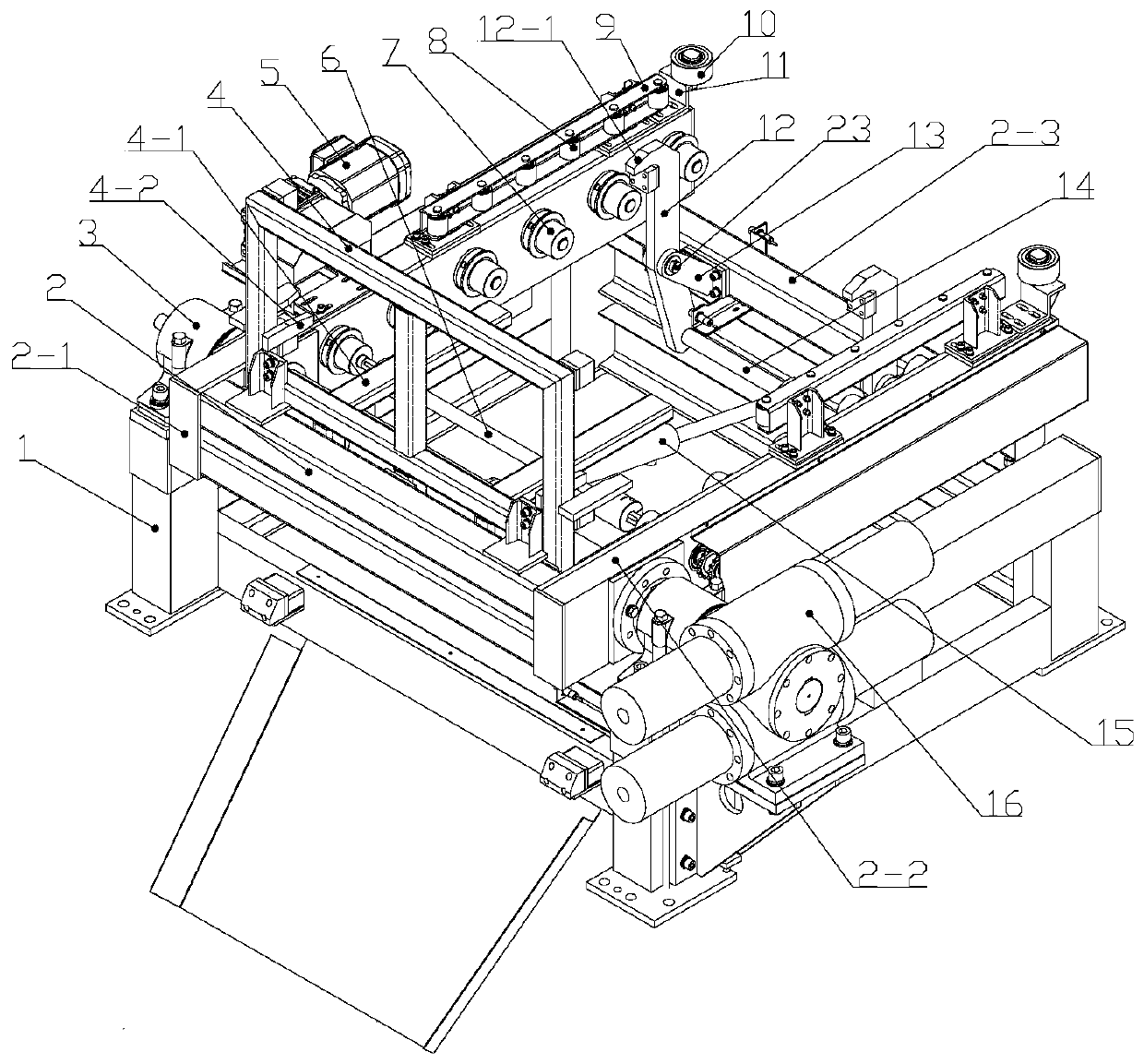
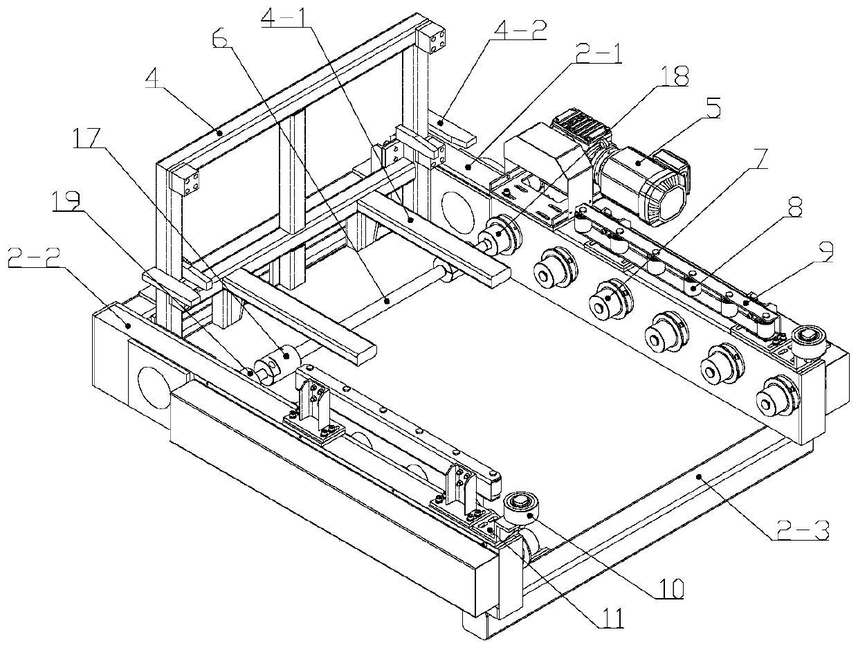
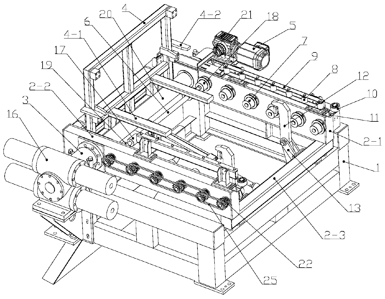
[0032] see Figure 1 to Figure 5 , an automatic clamping and turning machine for special containers for hazardous waste, comprising a base frame 1, the left and right sides of the base frame 1 are respectively provided with rotating shaft support seats 3, and the two rotating shaft support seats 3 jointly support a rotating shaft 20 through bearings. The lower end of the rotating shaft supporting seat 3 is fixedly connected with the longitudinal beam of the base frame 1, and the upper part of the rotating shaft supporting seat 3 is a bearing seat for installing bearings. One end of the rotating shaft 20 is fixedly connected to the output shaft of the swing hydraulic cylinder 16 installed on the base frame 1 in the circumferential direction, and the swing hydraulic cylinder 16 is installed on the mounting bracket provided on the side wall of the base frame 1, and one end of the mounting bracket is downward. The extension is fixed to the base frame 1, and the other end extends h...


PUM


Abstract

The invention provides a hazardous waste special container automatic clamping turnover machine. The hazardous waste special container automatic clamping turnover machine comprises a base frame. A rotary shaft is supported by two rotary shaft supporting bases on the base frame. One end of the rotary shaft is connected with an output shaft of a swing hydraulic cylinder. The rear ends of left and right longitudinal beams of a turnover frame at the upper end of the base frame are circumferentially fixed to the rotary shaft. The left longitudinal beam and the right longitudinal beam of the turnoverframe are each provided with a row of driving rolling wheels. The driving rolling wheels are supported onto the corresponding longitudinal beams through rolling wheel shafts. A double-row toothed chain wheel is mounted on each rolling wheel shaft. The adjacent double-row toothed chain wheels are connected through a chain. An output shaft of a driving motor of the turnover frame is connected withthe rolling wheel shaft of the first driving rolling wheel through a speed reduction mechanism. The rolling wheel shafts of the first driving rolling wheel and the second driving rolling wheel are connected through a transmission shaft. The lower end of a container locating rack at the rear end of the turnover frame is provided with forks. Hinge supports on a front cross beam of the turnover frameare hinged to the middle portions of clamping rotary arms. The upper portion of each clamping rotary arm is provided with a claw hook. Piston cylinders are hinged to hinged seats located on the rearside of the turnover frame. Piston rods of the piston cylinders are hinged to force arms located on the lower portions of the clamping rotary arms through second pin shafts.

Description

technical field [0001] The invention relates to the field of hazardous waste disposal devices, in particular to an automatic clamping and turning machine for special containers for hazardous waste. Background technique [0002] With the development of industry, more and more hazardous wastes are discharged in the process of industrial production, and the disposal of hazardous wastes has become more and more important. In the hazardous waste disposal industry, the hazardous waste needs to be poured into the mixing tank for stirring, and the pouring of the hazardous waste is realized by turning over the special container. At present, most of the turning over of hazardous waste containers is performed manually by the staff, which easily leads to direct contact between the staff and the hazardous waste, which is risky and endangers the physical and mental health of the staff. Although there is also a common turning machine for turning over at present, it is poured into the mixi...

Claims


Application Information

Patent Timeline
Patent Type & Authority Applications(China)
IPC IPC(8): B65G65/23
CPCB65G65/23
Inventor 邹坚罗勇应征夏辉伟李秋禹张奇
Owner CHONGQING LIYANG ENVIRONMENTAL PROTECTION TECH DEV
Learn More