A steel bar tightening device for construction

A steel bar and tightening technology, which is applied in the field of steel bar tightening equipment, can solve the problems of not being able to meet the needs of different diameters of steel bar binding and tightening, the limited adjustment of the binding gear, and the increase in the cost of iron wire.

Inactive Publication Date: 2021-06-18
THE FIRST CONSTR ENG COMPANY LTD OF CHINA CONSTR SECOND ENG BUREAU
View PDF13 Cites 0 Cited by
  • Summary
  • Abstract
  • Description
  • Claims
  • Application Information

AI Technical Summary

Problems solved by technology

[0002] In the process of building construction, it is necessary to weave and tie the lapped steel structure on the roof to facilitate better and safe concrete pouring construction. During the process of steel bar lapping, the two steel bars overlap each other and need to be connected by wire binding. , the steel bar connection method of binding with wires, most construction sites bind the steel bars manually, with the development of industrial manufacturing technology, a fully automatic steel bar tightening equipment, also known as a fully automatic steel bar binding machine, is a hand-held battery-type steel bar The fast binding tool can automatically complete all the steps of steel bar binding to replace manual binding of steel bars, but the existing automatic steel bar binding machine wastes iron wire compared with manual operation, and the cost of iron wire increases by 20-30%. The adjustment of the tightness of the bundling is limited, which cannot meet the needs of bundling and tightening of steel bars with different diameters. Therefore, it is necessary to develop a new type of steel bar tightening equipment for construction, in order to solve the problem of the existing automatic steel bar tightening equipment compared with artificial steel bars. The binding operation wastes iron wire, increases the cost of iron wire, and the adjustment of the tightness of the binding is limited, which cannot meet the needs of binding and tightening steel bars of different diameters

Method used


Image

  • A steel bar tightening device for construction
  • A steel bar tightening device for construction
  • A steel bar tightening device for construction

Examples


Embodiment

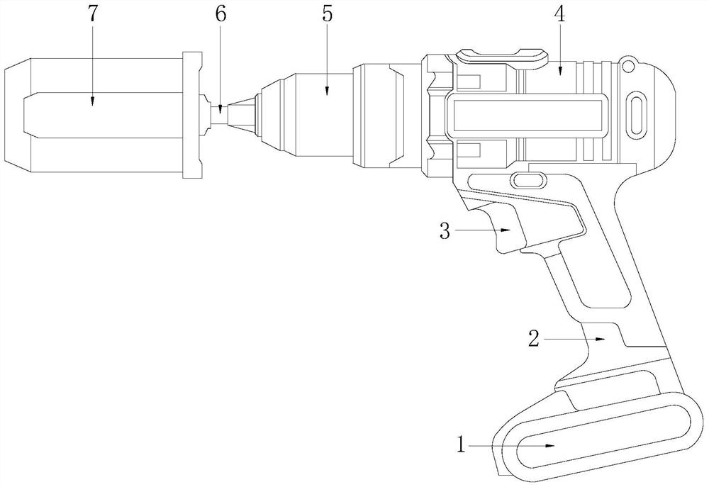
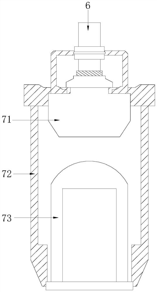
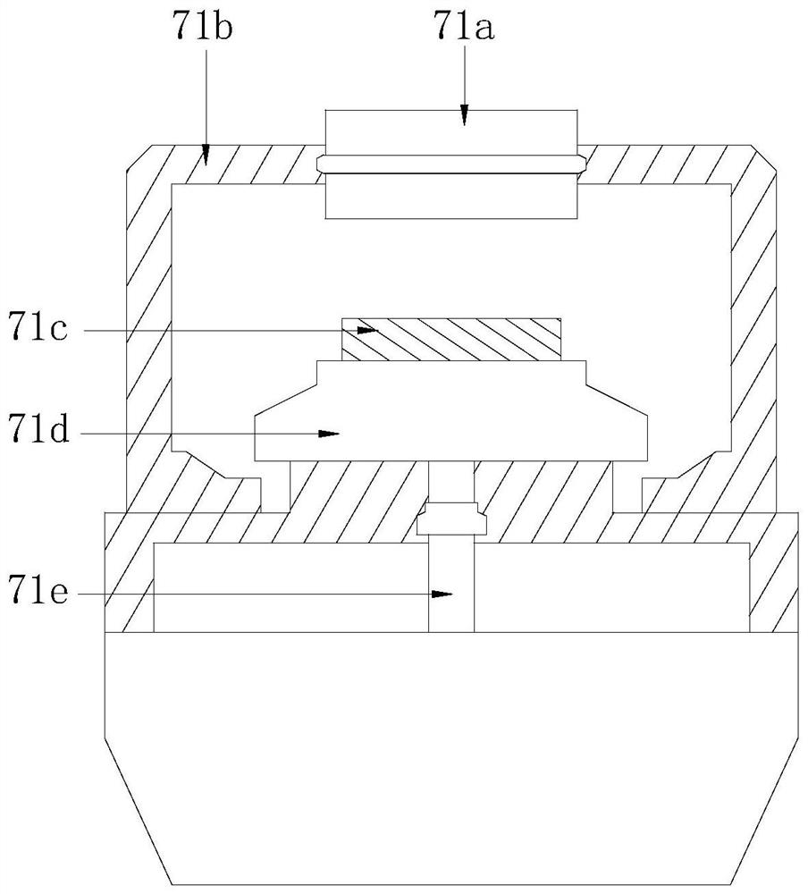
[0024] see Figure 1-6 , the present invention provides a specific embodiment of a steel bar tightening device used in construction;

[0025] see figure 1 , a steel bar tightening device used in construction, its structure includes a battery 1, a handle 2, a start button 3, an electric drill drive body 4, a coupling 5, a transmission shaft 6, and a wire binding device 7. The electric drill drives The bottom of the fuselage 4 is provided with a handle 2, the front end of the handle 2 is provided with a start button 3, and the bottom end of the handle 2 is provided with a battery 1, and the battery 1 is electrically connected to the electric drill drive body 4, and the The battery 1 and the handle 2 are movably connected, and the center position of the front end of the electric drill driving body 4 is provided with a coupling 5, and the coupling 5 and the electric drill driving body 4 are transmission connected, and the coupling The central position of the front end of 5 is pr...


PUM


Abstract

The invention discloses a steel bar tightening device used in construction. Its structure includes a battery, a handle, a start button, an electric drill drive body, a shaft coupling, a transmission shaft, and a wire binding device. The wire binding device consists of a shaft connection mechanism, Composed of a rotating sleeve and an iron wire twist knot tightening mechanism, the present invention has the effect: through the iron wire binding device, the tentacles at both ends of the untightened iron wire at the overlap of the steel bars are automatically moved by the front end of the upper push block and the lower push block. Attracted by permanent magnets, using the rotating force of the transmission shaft, the two ends of the iron wire are entangled with each other, forming a tight twist knot and fixed at the overlap of the two steel bars, so as to solve the problem of the existing automatic steel bar tightening equipment compared with artificial steel bars. The binding operation wastes iron wire, increases the cost of iron wire, and the adjustment of the tightness gear of the binding is limited, which cannot meet the needs of binding and tightening steel bars with different diameters.

Description

technical field [0001] The invention relates to the field of steel bar tightening equipment, in particular to a steel bar tightening equipment used in construction. Background technique [0002] In the process of building construction, it is necessary to weave and tie the lapped steel structure on the roof to facilitate better and safe concrete pouring construction. During the process of steel bar lapping, the two steel bars overlap each other and need to be connected by wire binding. , the steel bar connection method of binding with wires, most construction sites bind the steel bars manually, with the development of industrial manufacturing technology, a fully automatic steel bar tightening equipment, also known as a fully automatic steel bar binding machine, is a hand-held battery-type steel bar The fast binding tool can automatically complete all the steps of steel bar binding to replace manual binding of steel bars, but the existing automatic steel bar binding machine wa...

Claims


Application Information

Patent Timeline
Patent Type & Authority Patents(China)
IPC IPC(8): E04G21/12
CPCE04G21/123
Inventor 肖华成宋立博曹志浩马建剑谢理星
Owner THE FIRST CONSTR ENG COMPANY LTD OF CHINA CONSTR SECOND ENG BUREAU
Why Eureka
Try Eureka