Small water head water turbine blade profile
A water turbine and water head technology, which is applied in electromechanical devices, mechanical equipment, hydroelectric power generation, etc., can solve the problems of low energy utilization rate and achieve the effect of improving water flow utilization rate and high efficiency
- Summary
- Abstract
- Description
- Claims
- Application Information
AI Technical Summary
Problems solved by technology
Method used
Image
Examples
Embodiment 1
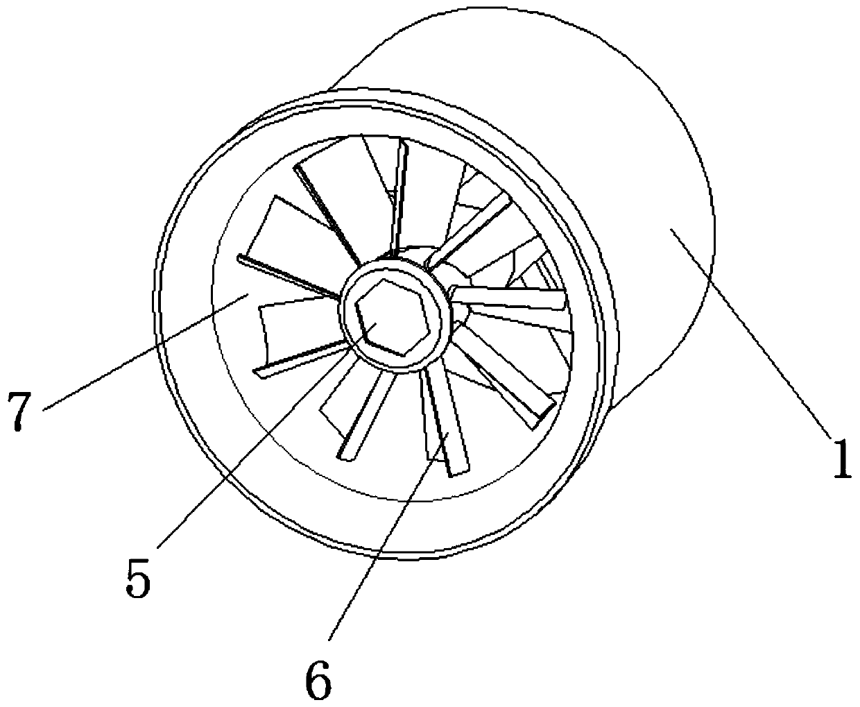
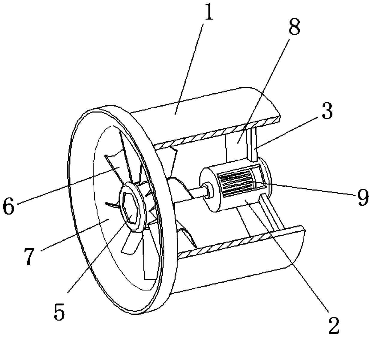
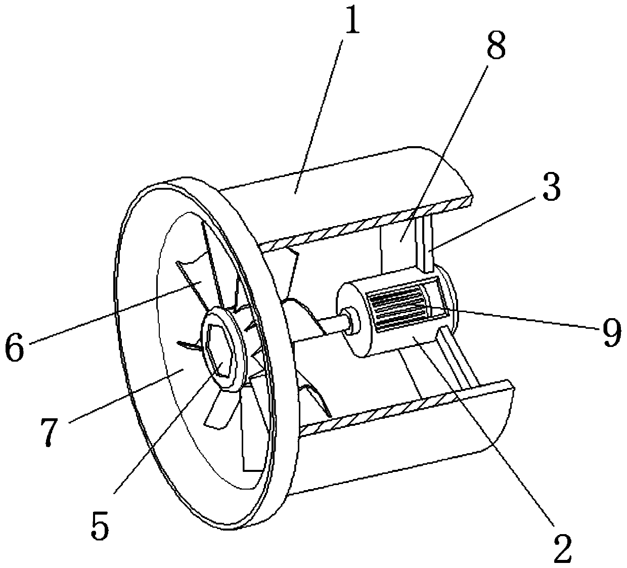
[0035] refer to Figure 1-2 , a small head water turbine blade type, including a fairing 1, the end of the fairing 1 located at the hub 5 is provided with a water inlet 7, the end of the fairing 1 far away from the hub 5 is provided with a water outlet 8, and the end of the fairing 1 inside is provided with There is a middle tube 2, and the outer wall of the middle tube 2 is provided with a number of straight rods 3, which are evenly distributed around the middle tube 2, and the straight rods 3 are all fixedly installed on the middle tube 2, and the number of the straight rods 3 is three , and the angle between two adjacent straight rods 3 is 120 degrees, and the end of the straight rod 3 away from the middle tube 2 is fixedly installed on the inner wall of the fairing 1, and the inside of the middle tube 2 is provided with a generator 9, The generator 9 is fixedly installed in the middle cylinder 2, the output end of the generator 9 is fixedly installed with the motor shaft 4...
Embodiment 2
[0038] As another preferred embodiment of the present invention, the only difference from the previous embodiment is that the diameter of the impeller is 150mm, the hub ratio is 0.4, the number of blades is 9 blades, and the positions of the five control points of the non-uniform rational B-spline curve of the blade inlet angle Coordinates, where the coordinates are in the form of (blade height percentage, blade inlet angle) followed by: (0%, -40.50°), (25%, -2.40°), (50%, 25.40°), (75%, 42.80 °), (100%, 53.00°); the position coordinates of the five control points of the blade outlet angle non-uniform rational B-spline curve, where the coordinates are in the form of (blade height percentage, blade outlet angle) in turn: (0%, 60.59°), (25%, 50.61°), (50%, 42.95°), (75%, 37.07°), (100%, 32.45°); 5 controls of blade chord length non-uniform rational B-spline curve Point position coordinates, where the coordinate form is (blade height percentage, blade chord length) in turn: (0%, ...
Embodiment 3
[0040]As another preferred embodiment of the present invention, the only difference from the previous embodiment is that the diameter of the impeller is 150mm, the hub ratio is 0.4, and the number of blades is 9. The position coordinates of the five control points of the non-uniform rational B-spline curve of the blade inlet angle, where the coordinates are in the form of (blade height percentage, blade inlet angle) as follows: (0%, -45.50°), (25%, -7.40 °), (50%, 20.40°), (75%, 37.80°), (100%, 48.00°); the position coordinates of the five control points of the blade outlet angle non-uniform rational B-spline curve, where the coordinate form is (Blade height percentage, blade outlet angle) are: (0%, 54.82°), (25%, 45.79°), (50%, 38.86°), (75%, 33.54°), (100%, 29.36° ); the position coordinates of the five control points of the non-uniform rational B-spline curve of blade chord length, wherein, the coordinate form is (blade height percentage, blade chord length) followed by: (0...
PUM
 Abstract
Description
Claims
Application Information
 - R&D
- Intellectual Property
- Life Sciences
- Materials
- Tech Scout
- Unparalleled Data Quality
- Higher Quality Content
- 60% Fewer Hallucinations
Browse by: Latest US Patents, China's latest patents, Technical Efficacy Thesaurus, Application Domain, Technology Topic, Popular Technical Reports.
© 2025 PatSnap. All rights reserved.Legal|Privacy policy|Modern Slavery Act Transparency Statement|Sitemap|About US| Contact US: help@patsnap.com


