Oil-gas separation device for air compressor

A technology for air compressors and separation devices, which is applied to the components of pumping devices for elastic fluids, mechanical equipment, machines/engines, etc., and can solve problems such as explosions, combustion of oil-gas separation devices, and blockage of oil-gas separation cores. Avoid collecting effects with too low strength

Active Publication Date: 2019-07-16
艾珍机械设备制造(上海)有限公司
View PDF6 Cites 0 Cited by
  • Summary
  • Abstract
  • Description
  • Claims
  • Application Information

AI Technical Summary

Problems solved by technology

[0002] The oil-gas separation device in the air compressor generally refers to the oil-gas separation core, which is one of the important components of the compressor. It is not ideal. If it is not replaced in time after long-term use, viscous sediment will be generated to block the oil-gas separation core, resulting in excessive oil content in the air or excessive

Method used


Image

  • Oil-gas separation device for air compressor
  • Oil-gas separation device for air compressor
  • Oil-gas separation device for air compressor

Examples


Embodiment

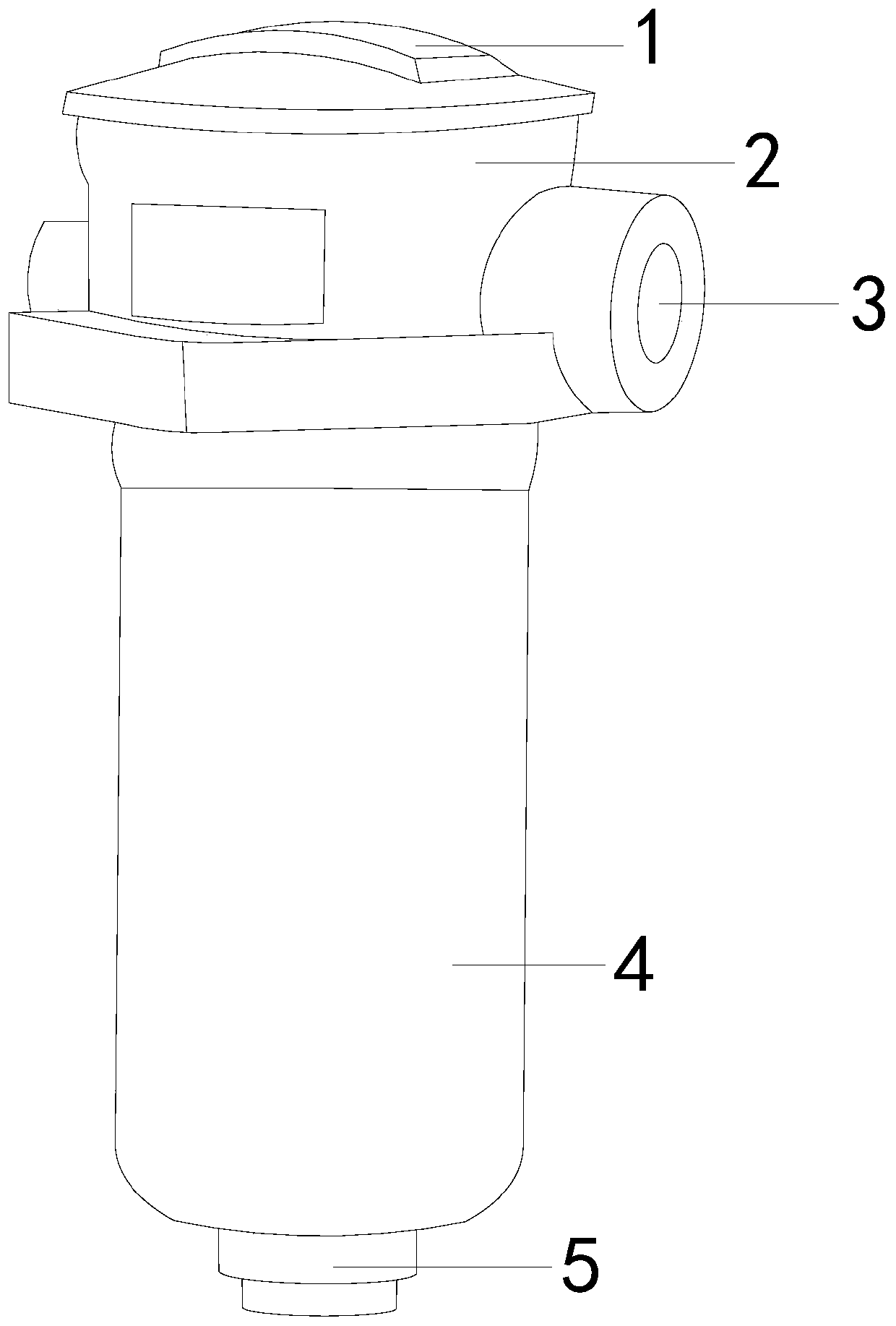
[0020] see figure 1 , the present invention provides an oil-gas separation device for an air compressor, the structure of which includes: a pressure control valve 1, an oil controller 2, a mist collecting mechanism 3, a device housing 4, and an oil return pipe 5. The pressure control valve 1 is connected to The oil controller 2, the oil controller 2 is connected with the mist collecting mechanism 3, the outer layer of the mist collecting mechanism 3 is sleeved with the device casing 4, and the bottom of the device casing 4 is connected to the oil return pipe 5, when the device starts to separate the oil and gas, the collecting The mist mechanism 3 is running to capture and collect the oil mist in the compressor. The pressure control valve 1 and the oil controller 2 are in the monitoring state at any time, and the mist collection mechanism 3 is continuously monitored to avoid overloading of the oil index of the device and over stressed.

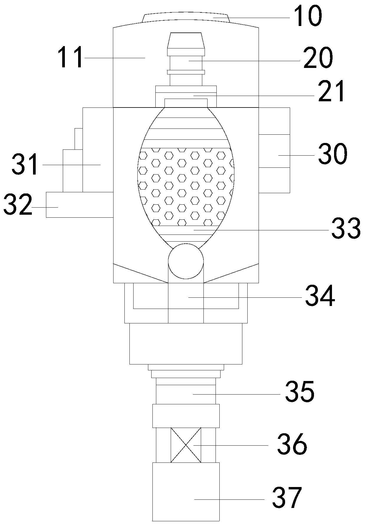
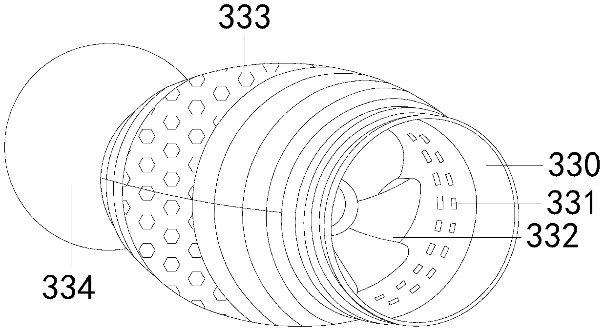
[0021] see figure 2 , Figure 5 , ...


PUM


Abstract

The invention discloses an oil-gas separation device for an air compressor. The structure of the oil-gas separation device comprises a pressure control valve, an oil controller, a mist collecting mechanism, a device housing and an oil return pipe. The oil-gas separation device has the following beneficial effects: by developing the mist collecting mechanism, an oil guide device in the mist collecting mechanism is used for achieving four mechanisms, i.e. capturing, collecting, filtering and precipitating of oil; the unique blade structures of eagle's beak-shaped blades in the oil guide device can not only generate a strong suction force to suck oil mist diffused in the compressor to the surfaces of the eagle's beak-shaped blades, but also guide collected oil to drip downwards smoothly; mostoil mist is collected through the oil guide device, and subjected to two times of filtration through a precipitator and three times of absorption through a filter cartridge, so that the oil content index of exhaust in the compressor can be ensured to be reduced to a minimum and thus to reach a safety index; and therefore, the problems that when the compressor uses the filter cartridge only, the capacity of collecting oil mist is too low and that because the filter cartridge is not replaced timely after being used for a long time, blockage is caused to lead to a serious accident are avoided.

Description

technical field [0001] The invention relates to the field of air-conditioning air compressor equipment, in particular to an oil-gas separation device for an air compressor. Background technique [0002] The oil and gas separation device in the air compressor generally refers to the oil and gas separation core, which is one of the important components of the compressor. It is not ideal. If it is not replaced in time after long-term use, viscous sediment will be generated to block the oil-gas separation core, resulting in excessive oil content in the air or excessive pressure difference. Use the oil-gas separation core to prevent The middle air filter can't filter the inhaled fine dust, and the effect of blocking the fine separation layer of the oil-gas separation core is better. Once the oil content of the exhaust gas is too large or the pressure difference is too large, it may even happen Combustion and explosion accidents of the oil-gas separation device. Based on the abov...

Claims


Application Information

Patent Timeline
IPC IPC(8): F04C29/02
CPCF04C29/026
Inventor 孙吉毅卢素珠谢安迪
Owner 艾珍机械设备制造(上海)有限公司
Why Eureka
Try Eureka