Unlock instant, AI-driven research and patent intelligence for your innovation.

Drying device

A technology of drying device and supply device, applied in heating device, drying solid materials, drying and other directions, can solve the problems of low sludge viscosity and inability to collect sludge P, achieve uniformity of water content, improve drying efficiency, The effect of optimizing the drying state

Inactive Publication Date: 2019-07-16
MITSUBISHI HEAVY IND ENVIRONMENTAL & CHEM ENG CO LTD
View PDF8 Cites 0 Cited by
  • Summary
  • Abstract
  • Description
  • Claims
  • Application Information

AI Technical Summary

Problems solved by technology

However, as described above, since the viscosity of the sludge is low at the time of input, the respective rotating shafts 105 cannot pick up the sludge P and move it to the opposite side.

Method used


Image

  • Drying device
  • Drying device
  • Drying device

Examples


no. 1 approach 〕

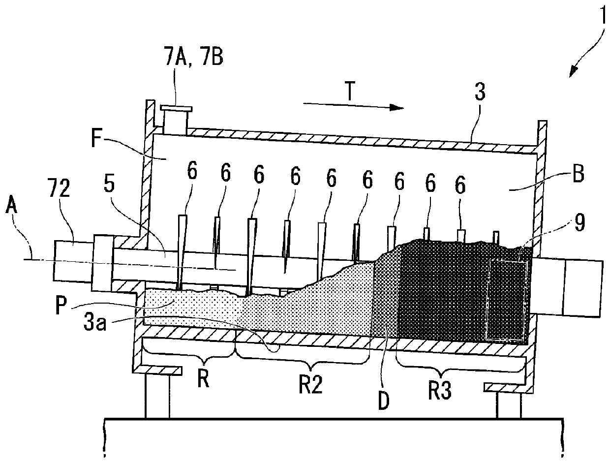
[0086] Hereinafter, a drying device 1 according to a first embodiment of the present invention will be described with reference to the drawings.

[0087] The drying device 1 of this embodiment is a highly viscous drying device for various biomass or waste such as sewage sludge, factory drainage sludge, food waste / kitchen waste, excrement sludge, livestock excrement, plant juice residue, etc. The water-containing matter (hereinafter referred to as sludge) is heated and dried (reduced moisture content) while being stirred and transported, so that they are discharged into powder and granular bodies. Sludge has, for example, a viscosity of 100 (Pa·s) or more and an ash content of 30 (%) or more.

[0088] In addition, as the measurement method of sludge, for example, if the ash content is used, the inorganic content in the input sludge solids can be obtained according to JIS M8812, and the viscosity measurement method can be obtained according to JIS K7199: Calculated in 1999 (ISO...


PUM


Abstract

The drying device (1) of the present invention has a casing (3) including a first inlet (7A) and a second inlet (7B), and a hydrate supply device (50) for supplying hydrate to the inlet (7A, 7B); a first rotating shaft group (21) comprising a plurality of rotating shafts that rotate rightward as viewed from the front side; and a second rotating shaft group (22) comprising a plurality of rotating shafts that is arranged at the right side of the first rotating shaft group (21) viewed from the front side and rotate leftward; and a control device (60). The first input port is disposed directly above the rotating shaft (5b) of the first rotating shaft group of the two closest rotating shafts; the second input port is disposed directly above the rotation axis (5c) of the second rotating shaft group (22) of the two closest rotating shafts. When the load of the rotating shaft of one of the rotating shaft groups (21, 22) is higher than a predetermined value, the control device is used to reduce the supply amount of the hydrate to one of the rotating shaft groups, and lower the rotational speed of one of the rotating shaft groups.

Description

technical field [0001] The present invention relates to drying devices. [0002] This application claims priority based on Japanese Patent Application No. 2017-252728 filed on December 28, 2017, and the content thereof is incorporated herein. Background technique [0003] Sludge composed of various biomasses, wastes, and other objects to be processed contains a large amount of water, and therefore may be subjected to drying treatment by heating using a drying device. [0004] The drying device is provided with a casing so as to descend toward the downstream side of the conveying direction. An inlet for throwing in sludge is formed at the upstream end of the casing. The sludge thrown into the casing is stirred by the disk member (a hollow disk member that performs indirect heating) installed on the outer periphery of the rotatable hollow shaft, while the conveying action based on the rotation of the disk member and the inclination of the casing Gradually move toward the do...

Claims


Application Information

Patent Timeline
Patent Type & Authority Applications(China)
IPC IPC(8): F26B17/20F26B23/00F26B25/04
CPCF26B17/20F26B23/00F26B25/04
Inventor 泽田和弥平山宗一郎三田村章弘
Owner MITSUBISHI HEAVY IND ENVIRONMENTAL & CHEM ENG CO LTD
Features
  • R&D
  • Intellectual Property
  • Life Sciences
  • Materials
  • Tech Scout
  • Unparalleled Data Quality
  • Higher Quality Content
  • 60% Fewer Hallucinations
Learn More