Method, device and system for designing free-form surface optical system, and storage medium

An optical system and free technology, applied in the field of free-form surface optical system, can solve the problems of relying on manpower, achieve the effect of reducing the demand for manpower, overcoming the lack of initial structure, and high imaging quality

Inactive Publication Date: 2019-07-16
ZHONGXIANGBOQIAN INFORMATION TECH CO LTD
View PDF6 Cites 10 Cited by
  • Summary
  • Abstract
  • Description
  • Claims
  • Application Information

AI Technical Summary

Problems solved by technology

[0003] This application provides a method, device, system and storage medium for designing a free-form optical system, so as to solve the problem that the design of a free-form optical system relies heavily on manpower

Method used


Image

  • Method, device and system for designing free-form surface optical system, and storage medium
  • Method, device and system for designing free-form surface optical system, and storage medium
  • Method, device and system for designing free-form surface optical system, and storage medium

Examples


Embodiment 1

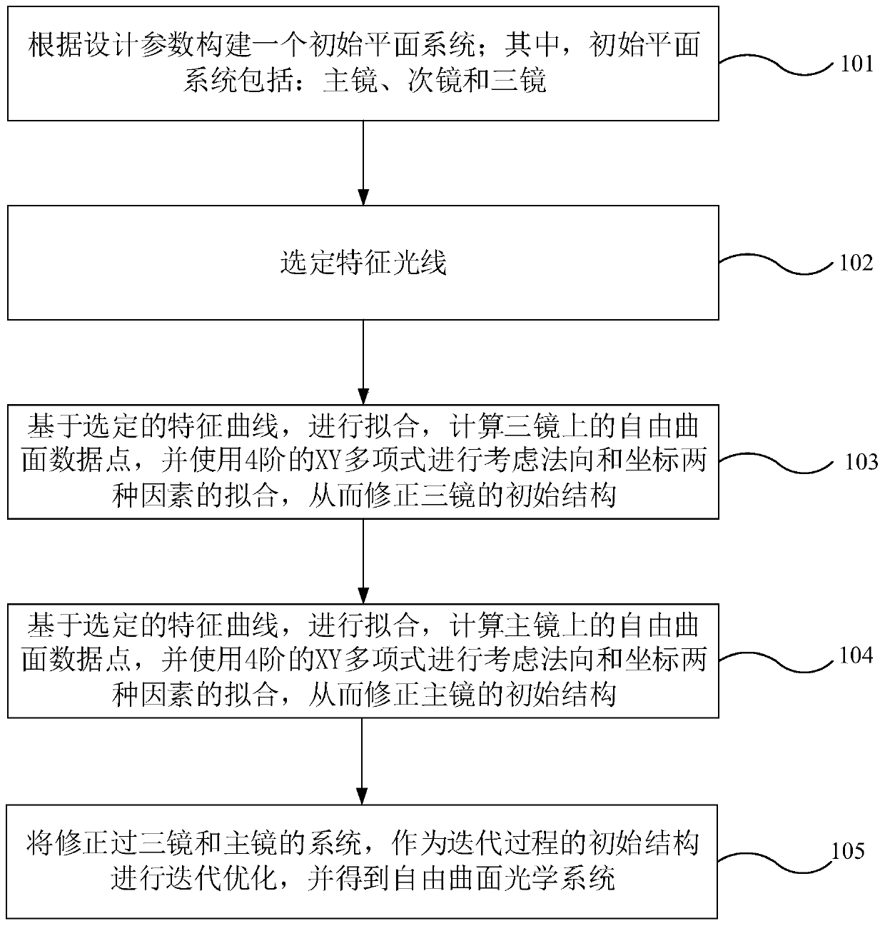
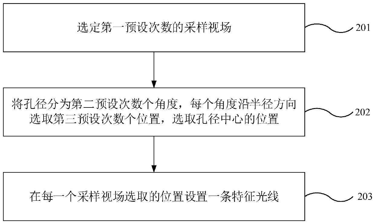
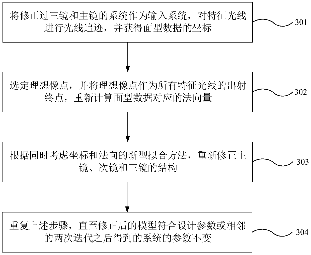
[0049] figure 1 A schematic flowchart of the method for designing an optical free-form surface optical system based on point-by-point calculation provided in Embodiment 1 of the present application; figure 2 A schematic flow chart of the method for selecting characteristic rays provided in Embodiment 1 of the present application; image 3 A schematic flow chart of the iterative method provided in Embodiment 1 of the present application; Figure 4 A planar system provided in Embodiment 1 of the present application; Figure 5 Another planar system provided in Embodiment 1 of the present application; Figure 6 Schematic diagram of feature light selection provided in Embodiment 1 of the present application; Figure 7 It is a schematic diagram of the fitting process provided in Example 1 of the present application.

[0050] refer to figure 1 , the method for designing an optical free-form surface optical system based on point-by-point calculation provided by this application ...

Embodiment 2

[0129] Figure 8 It is an optical free-form surface optical system design device based on point-by-point calculation provided in Embodiment 2 of the present application. Refer to Figure 8 , the point-by-point calculation-based optical free-form surface optical system design device provided by this application includes;

[0130] A construction module 81, configured to construct an initial planar system according to design parameters; wherein, the initial planar system includes: primary mirrors, secondary mirrors and three mirrors;

[0131] Selecting module 82, used for selecting characteristic rays;

[0132] The first fitting module 83 is used to perform fitting based on the selected characteristic curve, calculate the free-form surface data points on the three mirrors, and use the 4th-order XY polynomial to perform fitting considering two factors of normal and coordinates, Thereby modifying the initial structure of the three mirrors;

[0133] The second fitting module 84 i...

Embodiment 3

[0137] Figure 9 It is an optical free-form surface optical system design system based on point-by-point calculation provided in Embodiment 3 of the present application. Refer to Figure 9 , an optical free-form surface optical system design system based on point-by-point calculation, including: a memory 901 and a processor 902;

[0138] The processor and memory are connected by a communication bus:

[0139] Wherein, the processor is used to call and execute the program stored in the memory;

[0140] The memory is used to store a program, and the program is at least used to execute the method for designing an optical free-form surface optical system based on point-by-point calculation in Embodiment 1 of the present application.

[0141] Compared with the prior art, the design method of the free-form surface imaging optical system provided by the present invention can only use the initial system composed of simple planes as the input of the design, given the expected object-i...


PUM


Abstract

The invention provides a method for designing an optical free-form surface optical system based on point-by-point computation. The method comprises the following steps: constructing an initial plane system according to design parameters, wherein the initial plane system comprises: a primary mirror, a secondary mirror and a third mirror; selecting characteristic light; performing fitting based on aselected characteristic curve, calculating free-form surface data points on the third mirror, performing fitting, in which two factors, namely, normal and coordinates are considered, by using a four-order XY polynomial so as to correct the initial structure of the third mirror; performing fitting based on the selected characteristic curve, calculating the free-form surface data points on the primary mirror, and performing fitting, in which two factors, namely, normal and coordinates are considered, by using the four-order XY polynomial so as to correct the initial structure of the primary mirror; and performing iterative optimization by using the system in which the third mirror and the primary mirror are corrected as the initial structure of the iteration process, and obtaining the free-form surface optical system.

Description

technical field [0001] The present application relates to the technical field related to free-form surface optical systems, and in particular to a method, device, system and storage medium for designing a free-form surface optical system. Background technique [0002] In the existing design methods of imaging optical systems, the design process is generally to first find a good initial structure, and then perform computer-aided optimization. However, this design approach is not very smart or powerful enough. First, this design method is highly dependent on the initial structure, but the available initial structures are generally limited. If the structure and parameters of the initial structure are far from the design requirements, long-term optimization may be required. Moreover, for some imaging optical systems with advanced indicators and special structures, it may not be possible to find a suitable initial structure. In this way, the designer is likely to spend a lot of...

Claims


Application Information

Patent Timeline
Patent Type & Authority Applications(China)
IPC IPC(8): G02B27/00
CPCG02B27/0012
Inventor 张跃进展爱云李波胡勇黄德昌喻蒙
Owner ZHONGXIANGBOQIAN INFORMATION TECH CO LTD
Why Eureka
Try Eureka