Unlock instant, AI-driven research and patent intelligence for your innovation.

Power combination modular multi-level solid-state transformer topology structure for alternating-current and direct-current hybrid power distribution network

A modular multi-level, AC-DC hybrid technology, applied in the direction of converting AC power input to DC power output, output power conversion devices, electrical components, etc., can solve the problem of low transmission efficiency, power composite solid-state transformers rely on frequency selection equipment and solid-state transformers have many transformation stages, so as to achieve the effects of improved power transmission efficiency, increased power density and low cost

Active Publication Date: 2019-07-16
扬州永茂电力建设有限公司 +1
View PDF10 Cites 4 Cited by
  • Summary
  • Abstract
  • Description
  • Claims
  • Application Information

AI Technical Summary

Problems solved by technology

[0005] Purpose of the invention: Aiming at the problems that the existing solid-state transformers have many conversion stages and low transmission efficiency, and the existing power-combined solid-state transformers rely on frequency selection devices, the present invention proposes a power-combined modularization system for AC-DC hybrid distribution network Multilevel Solid State Transformer Topology

Method used


Image

  • Power combination modular multi-level solid-state transformer topology structure for alternating-current and direct-current hybrid power distribution network
  • Power combination modular multi-level solid-state transformer topology structure for alternating-current and direct-current hybrid power distribution network
  • Power combination modular multi-level solid-state transformer topology structure for alternating-current and direct-current hybrid power distribution network

Examples


Embodiment Construction

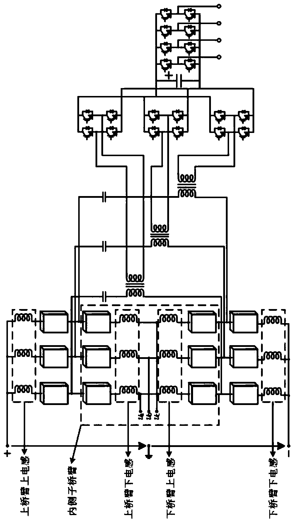
[0016] The technical solution of the present invention will be explained in detail below in conjunction with the drawings.

[0017] Such as figure 1 The power composite modular multilevel solid-state transformer topology structure of the present invention includes: a modular multilevel converter on the high voltage side, a high frequency AC-DC converter on the middle side, and an inverter on the low voltage side. Modular multilevel converters are used to convert high-voltage three-phase AC or high-voltage DC into high-voltage and high-frequency AC. The middle-side high-frequency AC-DC converter is used to convert the high-voltage and high-frequency AC obtained by the modular multilevel converter into low-voltage DC. The inverter is a three-phase four-wire half-bridge structure used to transform low-voltage DC into three-phase four-wire low-voltage AC. The modular multilevel converter and the high-frequency AC-DC converter are both three-phase structures, and each phase of the tw...


PUM


Abstract

The invention discloses a power combination solid-state transformer topology structure for an alternating-current and direct-current hybrid power distribution network. The structure comprises a modular multi-level converter located on the high-voltage side, a high-frequency AC-DC converter on the middle side and an inverter on the low-voltage side. One branch is led out from a middle point of eachof upper and lower bridge arms of three phases of the modular multi-level converter is connected into a high-frequency transformer through a blocking capacitor to form a new high-frequency power circulation path, and meanwhile, a high-frequency component is superposed in a target modulation signal; energy on the high-frequency side is introduced into the high-frequency transformer in a form of high-frequency power through the high-frequency circulation path and is transmitted to the low-voltage side, so that an input stage of the high-voltage side and an isolation stage of the middle side aresubjected to integrated power conversion by adopting a power combination thought, the power conversion stage number is effectively reduced, the power conversion is more integrated, and the power transmission efficiency is higher. Meanwhile, the high-frequency transmission power does not flow to a high-voltage direct-current port and a base-frequency alternating-current port, and a frequency selection device such as a wave trap or the like is not needed.

Description

Technical field [0001] The invention belongs to the technical field of high-voltage and high-power power electronics, and mainly relates to a power composite solid-state transformer topological structure for an AC-DC hybrid distribution network. Background technique [0002] In the traditional AC distribution network, the power transformer is the key equipment to achieve voltage level conversion and electrical isolation. However, due to its single function, the need for a large number of magnetic materials, and the inability to directly access or process DC power, it cannot meet future intelligence The demand of the distribution network, therefore, solid-state transformers based on fully-controlled power electronic devices came into being. [0003] Solid-state transformers, also known as power electronic transformers, electronic power transformers or smart transformers, were rated as one of the ten most promising technologies by MIT magazine in the United States in 2011, and are on...

Claims


Application Information

Patent Timeline
IPC IPC(8): H02M7/217H02M7/219H02M7/483H02M7/5387
CPCH02M7/2173H02M7/219H02M7/483H02M7/5387
Inventor 孙毅超丁楠木吕丹王琦
Owner 扬州永茂电力建设有限公司