Gas-liquid separation device for enhancing self-priming of self-priming multistage centrifugal pump

A technology of gas-liquid separation device and self-priming centrifugal pump, which is applied in the field of gas-liquid separation device and accelerated self-priming multi-stage centrifugal pump gas-liquid separation device, which can solve the problems of poor gas-liquid separation effect, poor self-priming stability, self-priming Slow suction speed and other problems, to achieve the effects of small loss of fluid kinetic energy, increased pressure, and increased air-carrying capacity

Active Publication Date: 2021-04-09
CHINA JILIANG UNIV
View PDF7 Cites 0 Cited by
  • Summary
  • Abstract
  • Description
  • Claims
  • Application Information

AI Technical Summary

Problems solved by technology

[0004] The purpose of the present invention is to provide a gas-liquid separation device that enhances the gas-liquid separation effect and accelerates self-priming for the current self-priming multi-stage centrifugal pump with poor gas-liquid separation effect, poor self-priming stability and slow self-priming speed.

Method used


Image

  • Gas-liquid separation device for enhancing self-priming of self-priming multistage centrifugal pump
  • Gas-liquid separation device for enhancing self-priming of self-priming multistage centrifugal pump
  • Gas-liquid separation device for enhancing self-priming of self-priming multistage centrifugal pump

Examples


Embodiment Construction

[0028]The present invention will be further described below with reference to the accompanying drawings and examples.

[0029]Next, a specific embodiment of the present invention is further described with reference to the accompanying drawings, but the present invention is not limited to these embodiments.

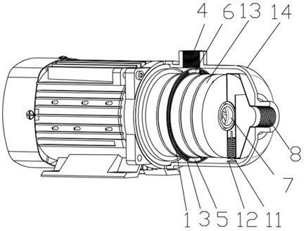
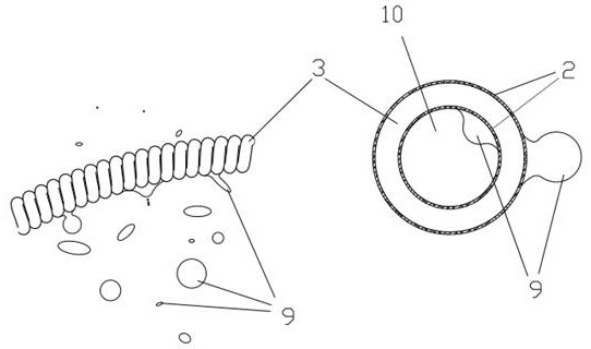
[0030]Such asfigure 1 As shown, the present invention is mounted between the self-suction centrifugal pump to promote the gas-liquid separation device between the pump casing cavity and the pump casing, which is an annular gas-liquid separation device that enhances gas-liquid separation and flow uniformity in the pump housing. . The gas-liquid separation device is composed of an annular spring 3 that is supported from the annular gas separation device and the annular spring 3 of the hydrophobic coating 2, and the annular spring bracket 1 is closely sticked together and is mounted at the centrifugal pump outlet 4.

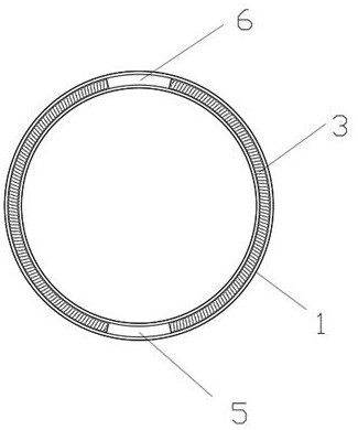
[0031]Such asfigure 2 As shown, the bottom end of the gas-liquid separati...


PUM


Abstract

The invention discloses a gas-liquid separation device for enhancing the self-suction of a self-suction multistage centrifugal pump. The gas-liquid separation device is arranged inside the self-priming centrifugal pump. The gas-liquid separation device is mainly composed of two parts: an annular bracket and a ring-shaped spiral channel installed close to the annular bracket. The surface of the spiral channel is uniform Coated with hydrophobic materials to form a ring-shaped spiral tube channel on the hydrophobic surface supported by a ring bracket; the above-mentioned gas-liquid separation device is installed between the cavity of the pump casing and the pump casing, and the inner and outer rings are tightly fitted to the cavity and the pump casing respectively. The top and bottom of the gas-liquid separation device are provided with fan-shaped openings, the top is the exhaust port, and the bottom is the water return port; the above-mentioned gas-liquid separation device is installed in the area near the pump outlet, so that the gas-liquid separation device The exhaust port faces the pump outlet, and the return port The water port is located at the bottom of the pump. The annular gas-liquid separation device of the present invention has the advantages of simple structure, convenient installation, low processing difficulty, light weight, easy access to raw materials, and broad application prospects.

Description

Technical field[0001]The present invention belongs to the field of fluid mechanical technology, and it is directed to a gas-liquid separation device, particularly for an air-liquid separation device that accelerates the self-suction multi-stage centrifugal pump.Background technique[0002]The pump is a widely used hydraulic machine, whether in the engineering or in life, it is inseparable from the pump. The centrifugal pump is a fluid machinery generated by the impeller rotation to transmit liquid fluid machinery, which is widely used in urban sewage, farmland irrigation, petroleum transport, marine ships and chemicals. The centrifugal pump is significantly advantageous in the mechanical structure, the advantage of the centrifugal pump is simple, and the application scenario is rich. The multi-stage centrifugal pump refers to the need for a long-term overlay in the fluid structure and above to meet the demand of high-rings in the actual project. Especially the small stainless steel mu...

Claims


Application Information

Patent Timeline
Patent Type & Authority Patents(China)
IPC IPC(8): B01D19/00
CPCB01D19/0005
Inventor 包福兵王舰航单佳明凃程旭尹招琴高晓燕陈强
Owner CHINA JILIANG UNIV
Why Eureka
Try Eureka