
Lifting mechanism for landing gear flexible intelligent mounting system

A technology of installation system and lifting mechanism, which is applied in the field of lifting mechanism, can solve the problems of limited use space, inconvenient maintenance and guarantee work, long working hours, etc., and achieve the effects of reducing storage space, convenient maintenance and repair, and simple structure

Pending Publication Date: 2019-07-19
SHENYANG FEIYAN AVIATION EQUIP
View PDF0 Cites 2 Cited by
  • Summary
  • Abstract
  • Description
  • Claims
  • Application Information

AI Technical Summary

Problems solved by technology

At present, the flexible landing gear installation system used for the installation and disassembly of aircraft landing gear is bulky, large in size, inflexible in movement, complex in operation, and difficult to control. The equipment needs to use an external power supply and air source when working, and the use site is limited. The degree of automation and intelligence is not high, and the installation and disassembly require a long working time, requiring the cooperation of multiple maintenance personnel, which brings a lot of inconvenience to the maintenance and support work, and does not meet the needs of the future operations of the army and the development of civil aviation maintenance equipment.

Method used


Image

  • Lifting mechanism for landing gear flexible intelligent mounting system
  • Lifting mechanism for landing gear flexible intelligent mounting system
  • Lifting mechanism for landing gear flexible intelligent mounting system

Examples


Embodiment Construction

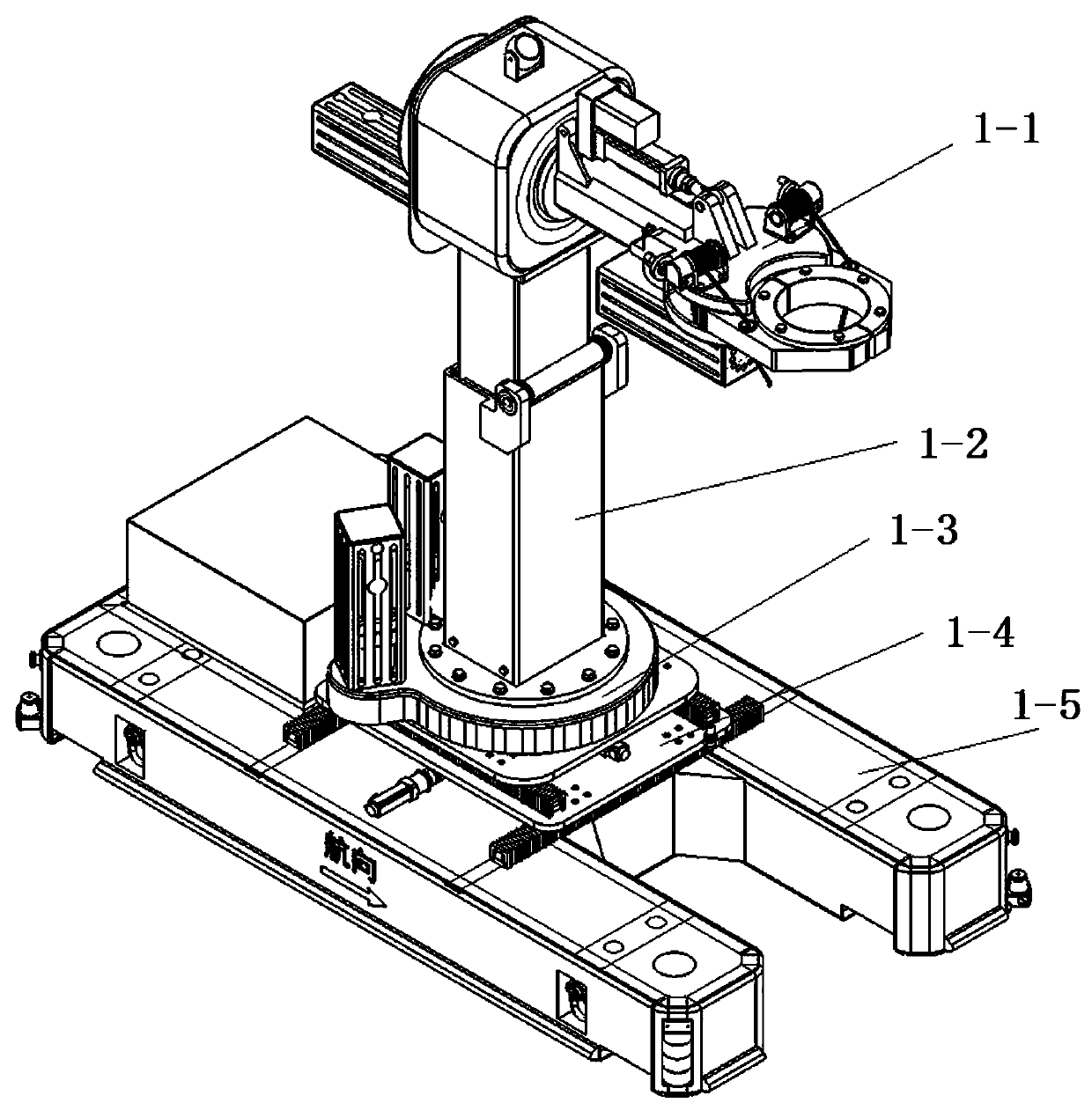
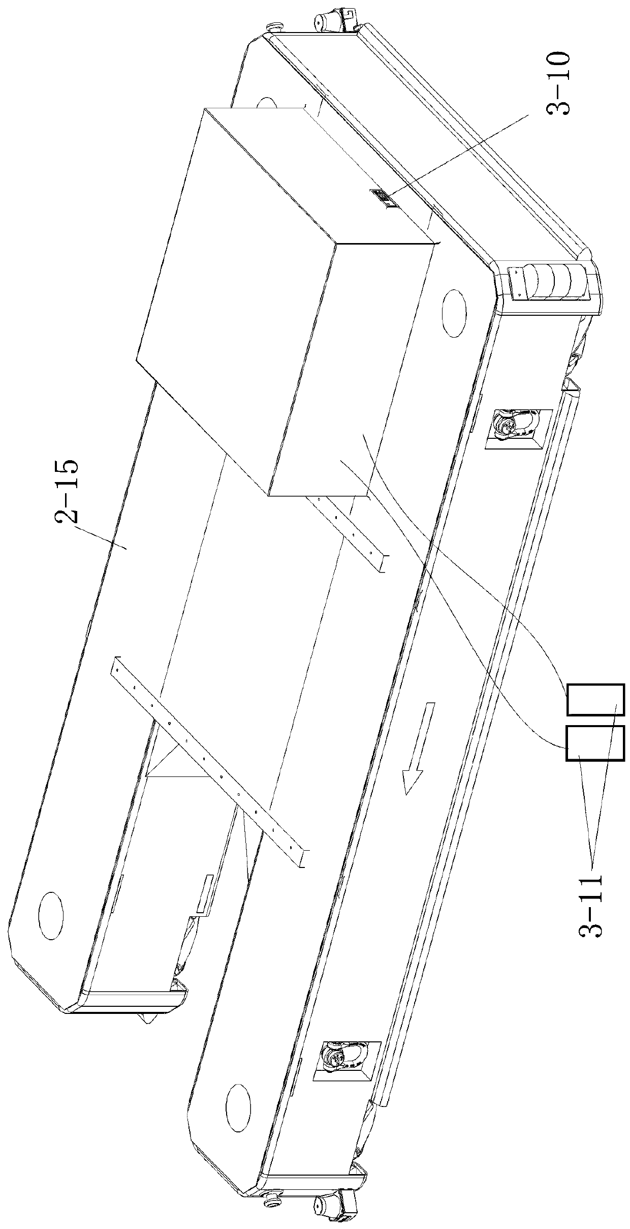
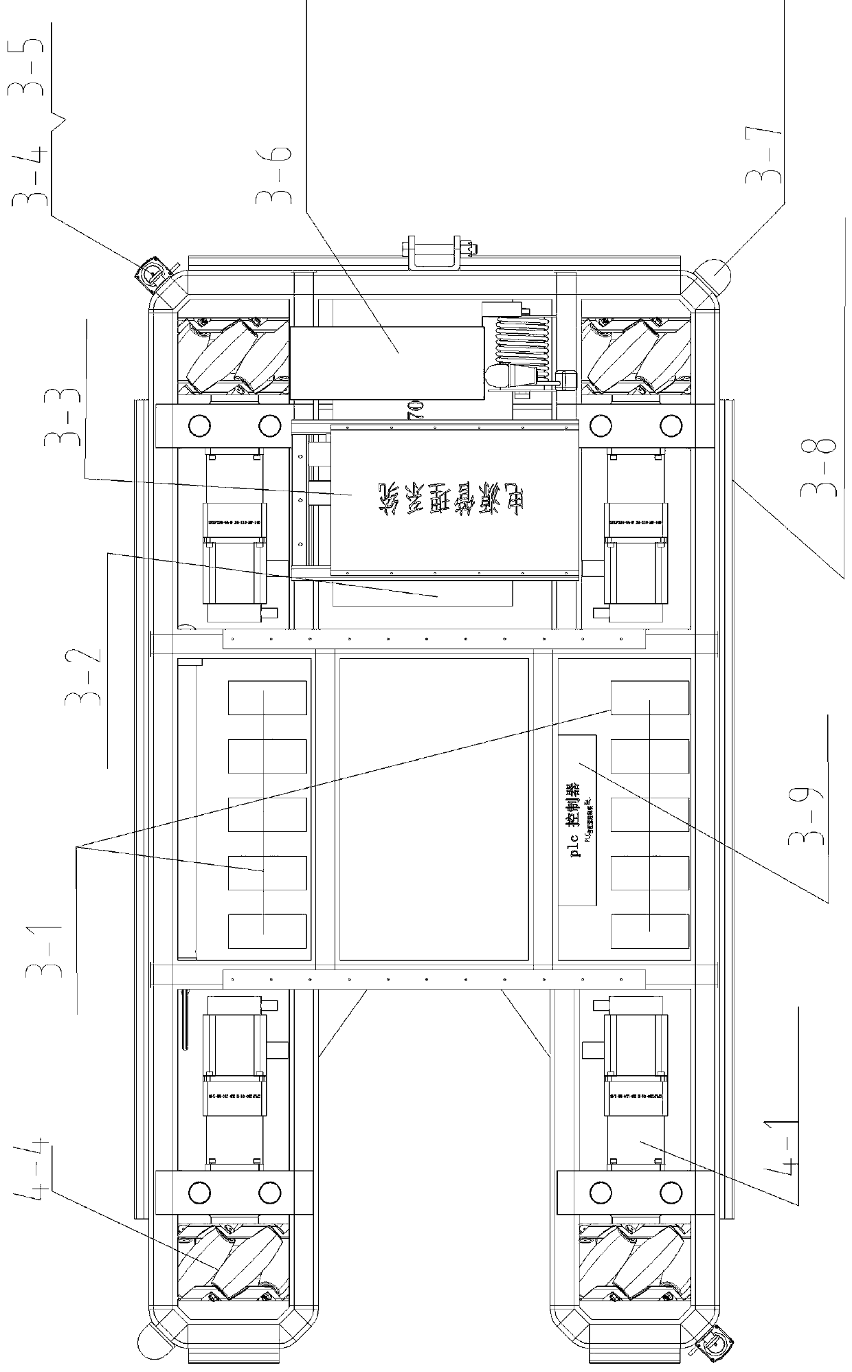
[0019] The flexible and intelligent installation system for aircraft landing gear includes a mechanical arm 1-1, a Z-axis lifting mechanism 1-2, a C-axis rotating mechanism 1-3, an XY translation mechanism 1-4, and a traveling vehicle 1-5.

[0020] The mechanical arm 1-1 includes a bearing seat 12-6, an electric push rod 12-8, a claw seat 12-12, a support arm 12-7 and a B-axis servo motor 12-1. A bearing 12-4 is installed in the bearing seat 12-6, the outer ring of the bearing 12-4 is fixedly connected with the inner wall of the bearing seat 12-6, and the support arm 12-7 is inserted into the inner ring of the bearing 12-4 and is fixedly connected. On the support arm 12-7, a B-axis gear 12-3 is sleeved by screws. The B-axis gear 12-3 is provided with a plurality of teeth in the set angle range, so that the support arm 12-7 can rotate within the set angle. The housing of the B-axis servo motor 12-1 is fixed on the bearing seat 12-6, and the gear on the power output shaft of th...


PUM


Abstract

The invention provides a lifting mechanism for a landing gear flexible intelligent mounting system. An external supporting cylinder is arranged on the external side of an internal movable cylinder ina sleeving manner; a Z-axis lead screw is vertically mounted on the internal wall of the external supporting cylinder through a lead screw mounting seat; a Z-axis nut is fixedly arranged on the internal wall of the internal movable cylinder; the Z-axis nut is arranged on the Z-axis lead screw in a sleeving manner and connected with the Z-axis lead screw through threads; one end of the Z-axis leadscrew is connected to a power output shaft of a Z-axis speed reducer through a Z-axis shaft coupling; and a power input shaft of the Z-axis speed reducer is connected to a power output shaft of a Z-axis servo motor. The lifting mechanism for the landing gear flexible intelligent mounting system is connected with a C-axis rotating mechanism through a bolt; during working, the C-axis rotating mechanism is used as support; with the C-axis rotating mechanism as a foundation, the internal movable cylinder of the lifting mechanism can realize lifting motion relative to the external supporting cylinder; as a telescopic lifting structure is adopted, the landing gear flexible intelligent mounting system reduces the integral height of equipment, and the lifting mechanism adopts a spiral lifter to lift the internal movable cylinder; and therefore, the structural form is simple, and equipment maintenance, maintenance and repair are convenient.

Description

technical field [0001] The invention belongs to the field of lifting mechanisms, in particular to a lifting mechanism for a landing gear flexible intelligent installation system. Background technique [0002] The flexible installation system of aircraft landing gear is an essential equipment for aircraft support equipment. Aircraft ground support equipment plays a very important role in ensuring the flight safety of the troops and completing training and combat tasks, and plays an indispensable role in realizing the inspection, maintenance, disassembly and assembly of aircraft on the ground. At present, the flexible landing gear installation system used for the installation and disassembly of aircraft landing gear is bulky, large in size, inflexible in movement, complex in operation, and difficult to control. The equipment needs to use an external power supply and air source when working, and the use site is limited. The degree of automation and intelligence is not high, an...

Claims


Application Information

Patent Timeline
Patent Type & Authority Applications(China)
IPC IPC(8): B64F5/10B64F5/40
CPCB64F5/10B64F5/40
Inventor 于忠杨青山吴殿宝潘高峰张景宇
Owner SHENYANG FEIYAN AVIATION EQUIP
Learn More